References
For a little more information on all this check out the following:
- Presentation for IEEE SoutheastCon 2014
- I2C specification
- BMP180 — barometer datasheet
- LSM303DLHC — accelerometer and magnetometer datasheet
- L3GD20 — gyroscope datasheet
- I2C device interface for userspace
Getting started
Pick up the following items.
- One Raspberry Pi with an USB power cable and an Ethernet cable
- One breadboard
- One BMP180 breakout
- One 9DOF breakout
- Wire
Listen to an overview of I2C using the IEEE SoutheastCon 2014 presentation.
A little system administration
Make sure you have the python-smbus package installed.
sudo apt-get install python-smbus
You must make sure you that the file
/etc/modprobe.d/raspi-blacklist.conf
does not blacklist the I2C driver.
If it does mention i2c-bcm2708,
be sure there is a # at the beginning of the line to comment
out the blacklisting of I2C.
Similarly, you must make sure that the following two lines appear in the /etc/modules file.
i2c-bcm2708
i2c-dev
Use the following commands to check if these files are properly configured.
…$ grep i2c /etc/modprobe.d/raspi-blacklist.conf
…$ grep i2c /etc/modules
If they are not properly configured you will have to use the nano editor with the sudo command to modify them.
…$ sudo nano /etc/modprobe.d/raspi-blacklist.conf
…$ sudo nano /etc/modules
You may need to install the
i2c-tools and libi2c-dev packages.
Since there is no harm in trying to install an already installed package,
go ahead and type the following command.
…$ sudo apt-get install i2c-tools libi2c-dev
Finally, to avoid all this sudo in
the future, add the user pi to the group
i2c.
…$ sudo adduser pi i2c
Now you need to shutdown your Pi.
…$ sudo shutdown -h now
Don’t turn off the power to your Pi until all you see only the red light on. Then wait another 30 seconds.
A little hardware configuration
Unplug the Raspberry Pi from power.
At this point, we need to do a little hardware configuration.
This isn’t hard for I2C.
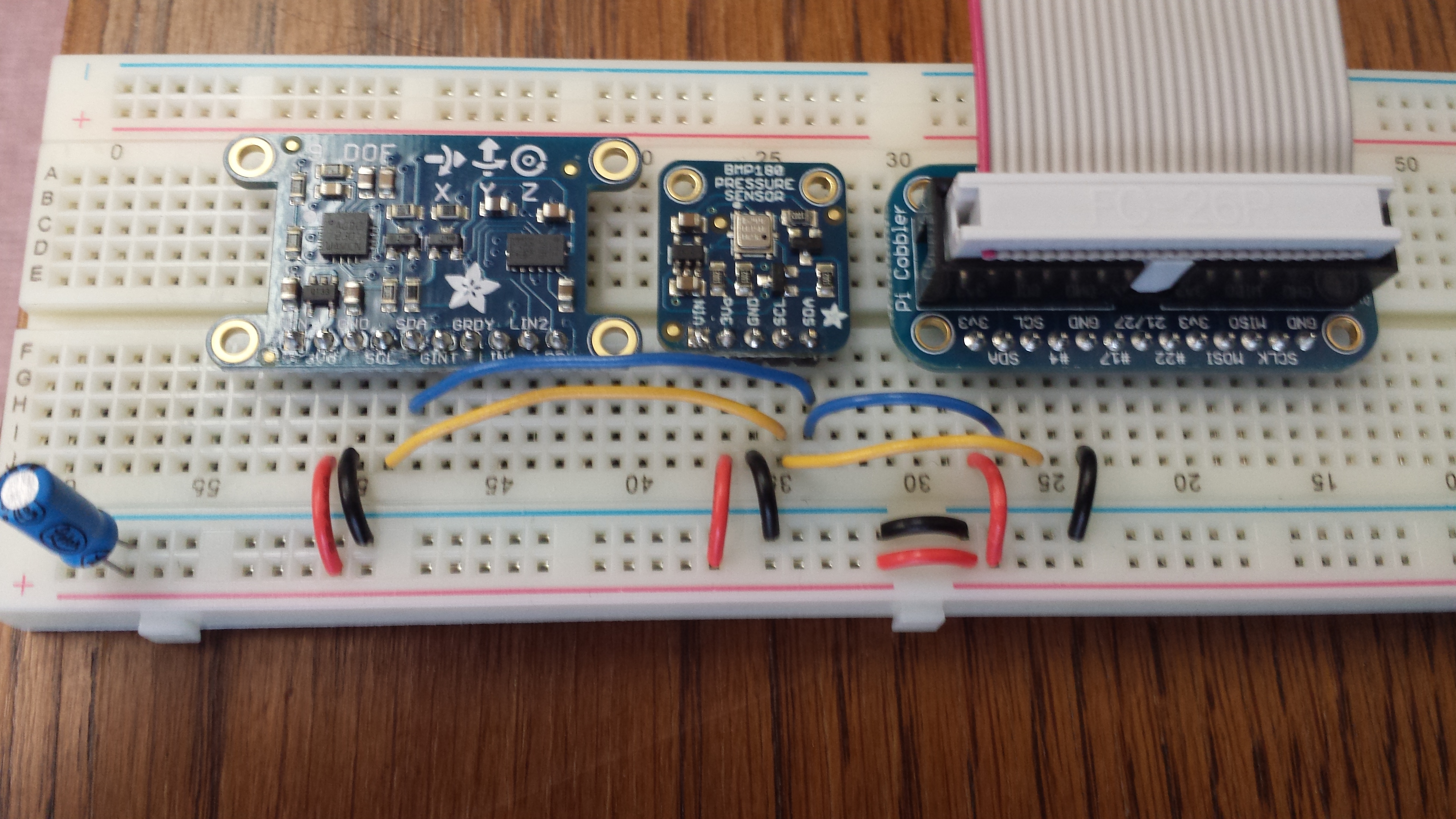
You need to place the
Pi Cobbler,
the BMP180 breakout,
and the 9-DOF IBM breakout
on the board.
It works best if you line them up so that the side of the
Cobbler with pins labeled 3V3 and SDA are
on the same size of the breadboard as the two breakout boards.
At this point, writing is pretty easy.
- Connect all the
3V3or3Vopins to the red power rail. - Connect all the
GNDpins to the blue ground rail. - Daisy-chain all the
SDApins. - Daisy-chain all the
SCKpins.
It should look something like the following picture.
There is only one way to plug that big cable into the Pi Cobbler.
However, when you plug the cable into the Raspberry Pi, the
side of the cable painted red must be near the Raspberry Pi pin labeled
P1.
Have the instructor check out your wiring before you reapply power to the Pi.
Verifying the kernel configuration
Power up the Raspberry Pi and wait about a minute after the Ethernet lights are on and settled before attempting to connect to the Pi. It take the Pi a little while to get the ssh daemon working.
Type the following command to make sure you are in the i2c
group and that the I2C device drivers are working.
…$ id
…$ lsmod | grep i2c
…$ ls -l /dev/i2c*
You should see something interesting for each of these commands.
Let’s make sure that the I2C devices are wired up. Type the following command to tell the system to scan I2C bus number 1.
…$ i2cdetect -y 1
The output of this command should look like the following. If it doesn’t, we have a problem.
     0  1  2  3  4  5  6  7  8  9  a  b  c  d  e  f
00:          -- -- -- -- -- -- -- -- -- -- -- -- --
10: -- -- -- -- -- -- -- -- -- 19 -- -- -- -- 1e --
20: -- -- -- -- -- -- -- -- -- -- -- -- -- -- -- --
30: -- -- -- -- -- -- -- -- -- -- -- -- -- -- -- --
40: -- -- -- -- -- -- -- -- -- -- -- -- -- -- -- --
50: -- -- -- -- -- -- -- -- -- -- -- -- -- -- -- --
60: -- -- -- -- -- -- -- -- -- -- -- 6b -- -- -- --
70: -- -- -- -- -- -- -- 77
This output tells us that there are four I2C devices.
| 19 | LSM303DLHC — accelerometer |
| 1E | LSM303DLHC — magnetometer(compass) |
| 6B | L3GD20 — gyroscope |
| 77 | BMP180 — barometer |
You really can’t go on until i2cdetect finds all the devices. If it doesn’t, either try again or find a partner.
Reading the temperature sensor from the shell
At this point we are going to use some I2C utilities to access the registers of the BMP180 to determine the temperature. The result will be a tad disappointing but it will illustrate what a C or Python program must do to obtain data from sensors. We are going to use i2cget and i2cdump to read from the BMP180 and i2cset to write to the BMP180.
Determining the device ID
The register with address 0xD0 should always
contain the value 0x55 on a BMP180. Be sure that it does.
…$ i2cget -y 1 0x77 0xD0 b
Reading the calibration registers
The BMP180 also contains some EEPROM registers that are set by the manufacturer to calibrate the BMP180. The datasheet of the BMP180 explains how these registers can be used, but it doesn’t explain what they represent. In any case, examine the mysterious EEPROM registers.
…$ i2cget -y 1 0x77 0xD0 b
Reading the temperature measurement register
To initiate a temperature measurement, you must write
0x2E to register 0xF4.
…$ i2cset -y 1 0x77 0xF4 0x2E
You can read the temperature at registers 0xF6
to 0xF7. Go ahead and try it out.
…$ i2cdump -y -r 0xF6-0xF7 1 0x77
Of course those numbers mean nothing to you. We’ll give you a program to interpret them in a minute. However, you can put your figure on the BMP180 and repeat the last two commands to see if the returned numbers change. (You’ll need to type the commands with your finger on the chip.)
Reading the temperature sensor with a program
That was hard. Let’s use a program this time. Start by copying over tar file containing a few programs to Pi. Since you need the program on your Pi and not your Linux workstation, just type the following commands into your Pi shell.
…$ wget http://www.cs.unca.edu/brock/classes/Spring2014/csci320/labs/csci320.tar.gz
…$ tar xfv csci320.tar.gz
…$ cd csci320
…$ ls -l
…$ make
The code
You should see four files in your csci320 directory.
- A C program for reading the temperature using the BMP180
- A Python program for reading the temperature using the BMP180
- A Python program for reading acceleration using the LSM303
- A Make file for building the C program
By the way, the make command command you typed earlier compiled your program.
Take a look at the C BMP180 program. It has the typical structure of a sensor-based program. It starts with a lot of register definitions for the sensor device, and then it contains code to read and write to the sensor registers.
In the middle of the program, you’ll see a mysterious sequence of C statements. These were copied directly from the BMP180 datasheet.
  ut = readBEWord(i2cfd, BMP180_READ_MEAS_REG) ;
  x1 = (ut-ac6)*ac5/32768 ;
  x2 = mc * 2048 / (x1 + md) ;
  b5 = x1 + x2 ;
  t = (b5 + 8) / 16 ;
At this time, also take a look at the other two programs: a Python program for reading temperature and a Python program for reading acceleration. The main job of all of these programs is to read and write registers from an I2C-based sensor.
Notice that all three programs return JSON-encoded data. This allows JavaScript programs to access the data over the internet. For example, the C BMP180 program is installed on a Raspberry Pi in my office and can report the temperature in my office right now.
Trying it out
For now just try out the program. Type the following command to read the temperature on the BMP180.
…$ ./bmp180json.py
Put your finger on the BMP180 and see if the temperature rises. If you have an ice cube, touch it to the BMP180. (No matches allowed in the building!)
Now try out the LSM303. First start it up.
…$ ./acclsm303.py
You should be able to tilt the breadboard and see some changes in the direction of acceleration.
What next
You could modify the programs so that they loop and give readings every few seconds, rather than giving a reading once and exiting.
You could read the datasheet for the LSM303DLHC and make a $80 compass.
You could sign up for CSCI 373.002 for the Fall 2014 semester and figure out how a gyroscope works.