Getting ready
You’ll need the following hardware for this lab.
- Raspberry Pi
- breadboard
- Pi Cobbler breakout
- BMP180 pressure sensor breakout
- Two LED’s
- Two 330 Ω resistors
- One push button switch
- Power supply (looks like a cell phone charger)
Physical connection
To get your Pi ready, do the following in the specified order.
- Make sure your Pi has a properly inserted SD Card.
- Connect your Pi to the CSCI VLAN using one of the pink Ethernet cables.
- Make sure everyone’s Pi setup looks like yours.
- Find a power strip and plug in your Pi power supply.
- Connect the micro-USB cable of the power supply to your Pi.
- Wait for the Ethernet link lights to turn on.
Monitor and keyboard connections
It is possible to connect to the Pi using the monitor, keyboard and mouse. However, that involves moving the USB cable from the workstation to the Pi. The CSCI 182 structure would be unhappy if you failed to reconnect them properly.
IP connection
Your Pi should have a letter written on its Ethernet port. The domain name of your Pi should be uncacsci-pi-λ.cs.unca.edu where λ is the letter on the Pi.
Use ssh to connect to your Pi using the password revealed by the instructor.
ssh pi@uncacsci-pi-λ.cs.unca.edu
If this doesn’t work, we really may have to connect the monitor.
Pi activities
Pause for a minute while everyone gets connected and we will take a look at an orientation presentation made by Rebecca Bruce and me at CCSC:SE 2014. We will pause around slide 22 for some activities.
Keep in mind that the Raspberry Pi is a Linux computer
running a real multi-user operating system. This is very different
that an Arduino.
During this lab we will occasionally use the Unix
sudo command which allows the
non-privileged user pi to execute commands as the
privileged user root.
We will avoid running commands as root!
Yes, this can be bothersome, but it is good practice for working in
the real world and allows you to call yourself a Linux
system administrator-in-training.
Wiring up the Cobbler
Now let’s wire up the Pi Cobbler.
- Place the Cobbler on the breadboard a little bit left of the middle.
- We use only one side of the Pi Cobbler, that side that has pins labeled 3V3. Wire the two 3V3 pins to the red bus on the breadboard with red wires and the two GND pins to the black (or blue) bus with black wires.
- If your breadboard has two pairs of buses on each side, make sure those two buss-es are connected.
- Connect an LED and resistor in series to test the power connection.
- Connect an LED and resistor in series from ground to Pin 17 of the cobbler.
- Connect the push-button switch between ground and Pin 22 of the cobbler.
It should all look at bit like
the right side of the picture below.
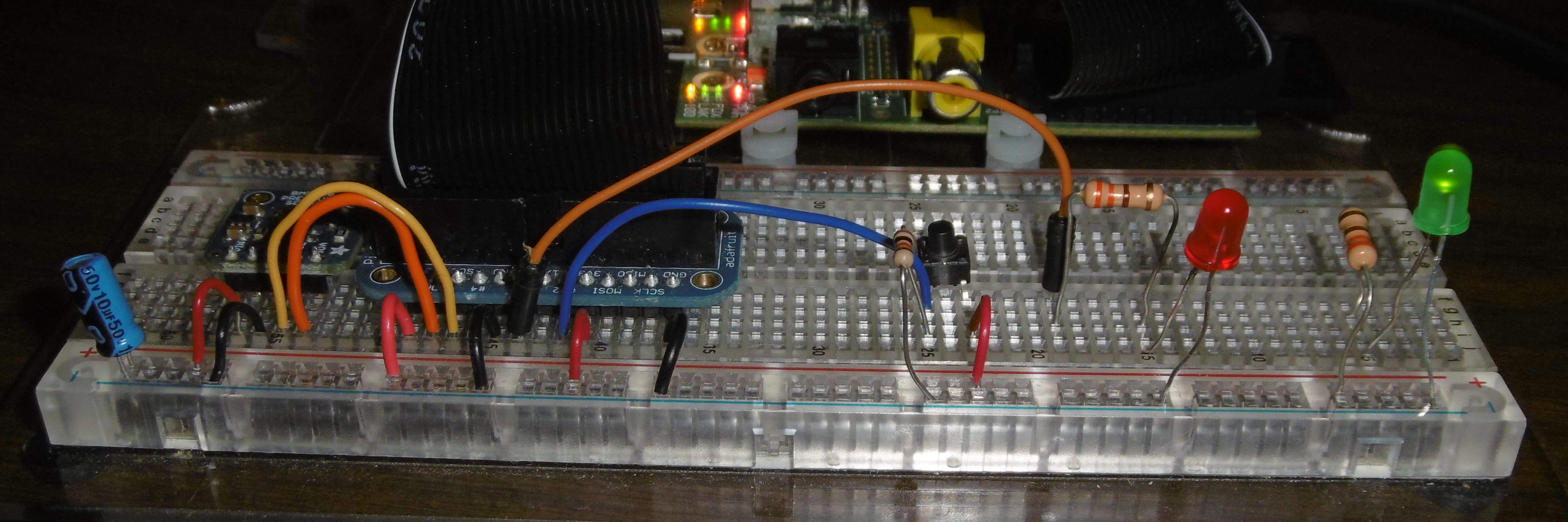
I will try to make some better pictures in lab.
After you have wired up the connector, compare your circuit with those around you. Be sure they all look the same.
Now connect the Pi to the breadboard using the Adafruit Pi Cobbler. Make sure the red or white edge of the ribbon cable is on the same side as Pin 1 of the Raspberry Pi.
Trying out the command line
On the Arduino, you wrote a program to read switches and turn on LEDs. We could write a program on the Raspberry Pi, but we are going to type shell commands that use the kernel’s GPIO Sysfs interface.
Following the directions of the instructor, type the following long sequence of commands to perform GPIO using the Linux GPIO device driver. There will be a lot of geek speak during this activity.
# list the gpio directory
ls -l /sys/class/gpio
# "export" pin 22, running as root
sudo sh -c "echo 22 > /sys/class/gpio/export"
# there should be a new subdirectory of /sys/class/gpio
ls -l /sys/class/gpio
# list files for controlling pin 22
ls -l /sys/class/gpio/gpio22
ls -lL /sys/class/gpio/gpio22
# determine the groups associated with this account
id
# allow users in group pi write access for files controlling pin 22
sudo chgrp pi /sys/class/gpio/gpio22/direction
sudo chgrp pi /sys/class/gpio/gpio22/value
sudo chmod g+w /sys/class/gpio/gpio22/direction
sudo chmod g+w /sys/class/gpio/gpio22/value
# check it out
ls -lL /sys/class/gpio/gpio22
# set Pin 22 for input
echo in > /sys/class/gpio/gpio22/direction
# read Pin 22
cat /sys/class/gpio/gpio22/value
# Wait five seconds and then read pin after you pressed the switch
sleep 5; cat /sys/class/gpio/gpio22/value
# Loop it and push it: hit Ctrl-C to stop
while true ; do cat /sys/class/gpio/gpio22/value ; sleep 1 ; done
# "export" pin 17, running as root
sudo sh -c "echo 17 > /sys/class/gpio/export"
ls -lL /sys/class/gpio/gpio17/
# allow users in group pi write access for files controlling pin 17
sudo chgrp pi /sys/class/gpio/gpio17/direction
sudo chgrp pi /sys/class/gpio/gpio17/value
sudo chmod g+w /sys/class/gpio/gpio17/direction
sudo chmod g+w /sys/class/gpio/gpio17/value
# check it out
ls -lL /sys/class/gpio/gpio17
# set Pin 17 for output
echo out > /sys/class/gpio/gpio17/direction
# turn LED on and off
echo 1 > /sys/class/gpio/gpio17/value
echo 0 > /sys/class/gpio/gpio17/value
# this is a one liner, though it could be spread over several lines
while true ; do cat /sys/class/gpio/gpio22/value > /sys/class/gpio/gpio17/value ; sleep 1 ; done
# do something else that is exciting
GPIO with a shell script
It is possible to place these commands in a shell script similar to blink.sh.
Consult the 916-page Advanced Bash-Scripting Guide for more information.
I2C
Look at pages 26 to 37 for a short introduction to I2C. We’ll do more in class soon.
Writing up an I2C sensor
Adafruit sells a large number of I2C breakout boards; however, if you ask, we will let you borrow some of ours, especially for senior projects.
- PCA9685 PWM/Servo Driver
- ADXL345 Accelerometer
- TPA2016 Class D Audio Amplifer
- LSM303DLHC accelerometer and magnetometer and L3GC20 gyroscope
- TSL2561 Light Sensor
- BMP180 Pressure/Temperature Sensor
These will also work on Arduinos when used with a bi-directional logic level controller.
Enabling I2C support on the Pi
There are few things we need to do to enable I2C support on the Pi’s operating system.
First, see if it is enabled by typing the following command:
ls -l /dev/i2c*
If you get a message about there being “No such file or directory”, your Pi is not yet configured for I2C. In that case, you need to follow the instructions in Adafruit’s Configuring I2C lesson, with the following exceptions.
- Use apt-get to install the
package
libi2c-devin addition topython-smbusandi2c-tools. - You do have to modify /etc/modules in the distribution we are running on the Pis.
- Do not reboot before modifying /etc/modules.
- You do not need to change /etc/modprobe.d/raspi-blacklist.conf or /boot/config.txt in our distribution.
- Add
pito groupi2cusing the command
sudo adduser pi i2c - Have someone check out your /etc/modules before you reboot.
After reboot, you should be able to type the following commands successfully. There is no point in continuing if they fail.
sudo ls -l /dev/i2c*
sudo i2cdetect -y 1
Wiring the I2C bus
You can remove the switch and LED, or you can just work around it.
In any case, write up the I2C bus. It’s not hard.
Only four wires are needed for each I2C module:
Two connect 3V3 and GND to the appropriate
power bus; and
the other two, SDA and SCL, form the
daisy chain of the I2C bus.
There is a picture on slide 30
of the orientation presentation.
Do the wiring with the breadboard disconnected from the Pi. Be sure to have someone check your wiring before connecting the breadboard and Pi.
After the connection has been made, the i2cdetect -y 1 should print something like the output shown below. The BMP180 is at bus address 0x77.
     0  1  2  3  4  5  6  7  8  9  a  b  c  d  e  f
00:          -- -- -- -- -- -- -- -- -- -- -- -- --
10: -- -- -- -- -- -- -- -- -- -- -- -- -- -- -- --
20: -- -- -- -- -- -- -- -- -- -- -- -- -- -- -- --
30: -- -- -- -- -- -- -- -- -- -- -- -- -- -- -- --
40: 40 -- -- -- -- -- -- -- -- -- -- -- -- -- -- --
50: -- -- -- -- -- -- -- -- -- -- -- -- -- -- -- --
60: -- -- -- -- -- -- -- -- -- -- -- -- -- -- -- --
70: -- -- -- -- -- -- -- 77
Difficult temperature reading
Open the BMP180 datasheet in another browser window. Let’s take a look at the slides on pages 39 to 42 of the orientation presentation. Note how the commands on page 42 relate to the program found on page 15 of the BMP180 datasheet.
Read the temperature from the command line. It’s 0x77 because that’s the I2 address of the BMP180.
# Make sure you have a BMP180
i2cget  -y 1 0x77 0xD0 b
# Examine mysterious EEPROM calibration registers
i2cdump -r 0xAA-0xBF -y 1 0x77
# Examine measurement register
i2cdump -y -r 0xF4-0xF7 1 0x77
# Tell device to read temperature
i2cset  -y 1 0x77 0xF4 0x2E
# Read the temperatur
i2cdump -y -r 0xF4-0xF7 1 0x77
Put your finger on the BMP180 sensor, repeat the last two commands and see if the results changed. (Use the up-arrow key to recall previous commands.)
I2C based programming
Yes, there is a better way! You can write programs.
Execute the following commands to copy a tar file to your Pi then un-tar it.
wget http://www.cs.unca.edu/brock/classes/Fall2015/csci255/labs/raspberrypi/i2cjson.tar
tar xfv i2cjson.tar
cd i2cjson
Compare the C program for reading temperature from the BMP180 and the Python program for reading temperature with the sample code in the BMP180 datasheet.
C-based temperature reading
At the command line, run the program make to recompile the program. make is a Unix command for the “smart” building of programs. It is used heavily in both NetBeans and MPLAB X.
This Makefile is pretty simple. The ones generated by NetBeans and MPLAB X are pretty complex. See if you can figure out what Makefile does. In the past, students in CSCI 202 created many files like these.
all:		bmp180json

bmp180json:	bmp180json.c
	gcc -o bmp180json -DI2CBUSNUM=1 bmp180json.c
Run the bmp180json program.
Open
bmp180json.c
with the nano and
change the oversampling rate, OSS,
for the BMP to 3.
Does that make the reading any more accurate?
Python-based sensor reading
Now take a look at the bmp180json.py program. You can also run it. Python seems to be the most popular choice for programming on the Pi. The output of this program is an HTTP header followed by an object specified in JSON. This is very useful for web based applications.
pinkie-pie.cs.unca.edu is a Raspberry Pi with 256Mbytes of RAM that runs a web site and a CGI Python script to return the temperature in RRO 221.
A better way
bmp180json.py was written before the Adafruit library for the BMP180 on the Raspberry Pi was available. adabmp180json.py is a much simpler program that uses the Adafruit library.
Unfortunately, the Adafruit library structure has changed slightly since this program was written. If you have time, search the Adafruit’s GitHub repositories for the updated library and modify adabmp180json.py to use the new library.