So far in working with the PIC24 processor, we have learned to how to control digital input/output and analog input. In this lab, we will learn about interrupts while using a rotary encoder. Rotary encoders detect shaft rotation and they are used in a multiplicity of applications ranging from volume knobs to motor feedback. We will use a rotary encoder to drive sound and light output.
You should be already familiar with interrupts; they are discussed in Ch 9 of your textbook. In this lab, you will study them in action. We won't be writing interrupt service routines (ISRs), but rather using those provided in the example code archive and understanding how they work. As a first step in that process, view the silent tutorial on "traps." Traps are non-maskable, internally-generated interrupts. Once you're watched the tutorial, open and run the chap9/trap_test.mcp, and chap9/trap_test_handled.mcp projects, successively, and observe the interrupt performance described in the tutorial.
| Explain to your instructor the difference between trap_test.c and trap_test_handled.c. Also explain how the ISR is called in both programs. |
A rotary encoder indicates shaft rotation by toggling the output of two pins (A and B) from high to low or vice-versa, the direction of rotation is indicated by which line goes high (or low first) as shown in the following diagram from wikipedia:
The output above is typical of a Gray code rotary encoder. Counterclockwise rotation of the shaft produces the sequence: 00, 01, 11 and 10, while counterclockwise rotation generates 00, 10, 11, and 01. In a Gray code, adjacent encodings differ by only one bit position and the rotation direction can be determined by comparing the current 2-bit value with the last value.
Because an encoder's output is generated by switch opens and closures, it is subject to switch bounce. Switches don't open and close cleanly on the millisecond time scale. Instead, a typical switch makes multiple transitions during the tens of milliseconds required to open or close; this is due to various effects including age, operating inertia, mechanical design, and the microscopic condition of the switch-contact surfaces. For this reason, it is difficult to use Change Notification Interrupts or INTx Interrupts for processing switch input events. A simpler approach, is to use interrupts to check the status of the switch. The rotary encoder program in the example code archive uses a Periodic Timer Interrupt (as discussed in Ch 9) to read the rotary encoder output.
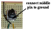
Install your rotary encoder on your PIC24 development board as shown below. As shown, the encoder support arms sit in the grove between rows of the breadboard. As indicated below, the middle pin of the encoder connects to ground and the two outer pins connect to the PIC24 to provide shaft position information.
Open the chap9/rot_enc.mcp project and connect the encoder output pins to the specific PIC24 pins used in the program. Run the program and verify that the program produces the expected output. Ask your instructor if you need help.
Once you understand the output of rot_enc.mcp, modify it so that the range of output values is 0-255, the max that can be stored in an 8-bit variable. Also make the first output value be 127, the middle of the output range. HINT: As described in Fig 9.25 of your text, ROT_MAX establishes the max allowed counter value, and the initial value of the counter variable, u8_cntrROT, is the first output value.
| Show your instructor the output of your modified rot_enc.mcp program. |
Before we add sound to our project, let's spend a bit more time understanding the rot_enc.c program. Figure 9.25 of your text is an annotated listing of that program, check it out if you have your text handy.
There are six procedures written as part of rot_enc.c, they are: processRotaryData(), GET_ROT_STATE(), configRotaryEncoder(), _T3Interrupt (), configTimer3(), and main(). You should be able to explain the function of each of those procedures. You should understand exactly how the ISR for the timer is used to poll the rotary encoder.
| Explain each procedure in rot_enc.c to your instructor. |
Now that you understand rot_enc.c, we can modify it further. Let's begin by using the rotary encoder to control the tone sent to the speaker connected to pin RB14. If your have removed your amplifier and speaker assembly, please recreate it using Lab 12 as your guide. Your job in this lab is to create something like a "rotary encoder theremin," by taking code from theremin.c and adding it to rot_enc.c. Of course, there is a little bit more to it, but not much. Give it a try.
| Demonstrate your rotary encoder theremin for your instructor. |
As the grand finale, modify the code to change the rate at which the LED on pin RB15 blinks. Make the speed of its state change (i.e., blinking) be controlled by the rotary encoder. You can revisit chap8/ledflash.mcp to find the correct macros for configuring the LED pin. The challenge is to delay flipping the state of the LED by an amount that is proportional to the position of the rotary encoder while still maintaining steady tonal output to the speaker. HINT: Use the duration of the tone sent to the speaker to delay the state change of the LED.
| Demonstrate your rotary encoder sound and light device for your instructor. |