CSCI 255 Lab
Lab 13 -- PWM and Analog Input
Part 0: Setup
We'll be using the amplifier and speaker circuitry from
Lab 12 for this exercise as well.
If you don't have that assembly, begin by creating it using the instructions in
Lab 12.
Part 1: Playing with Frequency
Below is the playTone() function that we wrote in Lab 12. With SPEAKER defined to
be _LATB14, playTone() outputs a square wave with the same frequency as the input note
(i.e., the value of the parameter called tone). Use the code provided below, if your playTone()
function is different.
void playTone(uint16 tone, uint32 duration) {
// tone is the tone frequency in cycles per second
// duration is the length of time the tone is played
// in milliseconds
	uint32 pulseLength_us = 1000000 / (2 * tone);
	uint32 i, duration_us = duration*1000;

	if (tone) {
		for (i=0; i < duration_us; i += 2*pulseLength_us) {
			SPEAKER = 1;
			DELAY_US(pulseLength_us);
			SPEAKER = 0;
			DELAY_US(pulseLength_us);
		}
	}
	else {
		DELAY_MS(duration);
	}
}
In the next series of steps we will investigate using square-wave output to simulate analog output.
Begin by connecting a LED to pin RB14 as shown below.

- Now run
music.c (with the version of playTone() provide above) on your PIC processor. Notice that
the LED is illuminated for the entire duration of each note. It is not apparent that the LED is actually
receiving a pulsing signal (i.e., high/low pulses at the frequency of the note being played). Can you
speculate as to why this is true?
- If you guessed that the pulses are too quick for our eyes to see, you'd be on the right track. Try
making the pulses visible by playing the lowest note in
pitches.h. To do this, you might modify
music.c to look something like this.
	// the notes in the song to be played using the definitions in pitches.h
	  uint16 melody[] = {NOTE_D8, NOTE_B4, NOTE_B0};  // B0 is the lowest note in pitches.h

	// note durations: 4 = quarter note, 8 = eighth note, etc.:
	  uint16 noteDurations[] = {1, 1, 1};

	// number of notes in the melody array
	  uint16 numberNotes = 3;
You should be able to see the LED pulsing when you play B0, but not the higher notes. To make the
pulsing more noticeable you could try lowering the frequency further, for example:
	// the notes in the song to be played using the definitions in pitches.h
	  uint16 melody[] = {NOTE_D8, NOTE_B4, (NOTE_B0/4)};  // B0 is the lowest note in pitches.h

	// note durations: 4 = quarter note, 8 = eighth note, etc.:
	  uint16 noteDurations[] = {1, 1, 1};

	// number of notes in the melody array
	  uint16 numberNotes = 3;
The lower the frequency, the more visible the pulses.
Driving a device, like a LED, with a signal pulsing at a high frequency can be useful. We can effectively
reduce the voltage that we send to a device by providing on-off pulses at a frequency far above the devices
response rate. Consider that picture below.

Averaged over time, the 50% duty cycle provides one half the voltage provided by the 100% duty cycle, and the
20% duty cycle provides only 20% of the voltage provided by the 100% duty cycle. Pulse Width
Modulation or PWM is a technique for producing variable voltage output by changing the duration of the high pulse
in a square wave of fixed frequency---the shorter the high pulse, the lower the effective voltage.
In short, PWM is a form of analog output that can be generated by a digital device. Pulse width
modulation is a form of Digital-to-Analog Conversion or DAC.
Let's try it ourselves. Modify the function playTone() (our square wave generator) to allow variable length
high pulses so that we can generate different duty cycles. To do this, add a new parameter,
shorten, to the function. The larger the value of shorten, the shorter the high pulse
of the square wave.
void playTone(uint16 shorten, uint16 tone, uint32 duration) {
// tone is the tone frequency in cycles per second
// duration is the length of time the tone is played
// in milliseconds

	uint32 pulseLength_us = 1000000 / (2 * tone);
	uint32 i, duration_us = duration*1000;
	uint32 pulseLengthHigh = pulseLength_us/shorten ;
	uint32 pulseLengthLow  = 2*pulseLength_us-pulseLengthHigh ;

	if (tone) {
		for (i=0; i < duration_us; i += 2*pulseLength_us) {
			SPEAKER = 1;
			DELAY_US(pulseLengthHigh);
			SPEAKER = 0;
			DELAY_US(pulseLengthLow);
		}
	}
	else {
		DELAY_MS(duration);
	}
}
Of course, you also have to modify the call to playTone() to include a value for
shorten, AND you have to change the function prototype for playTone() located
at the beginning of the program.
playTone(4, melody[thisNote], noteDuration); // call to playTone()
void playTone(uint16, uint16, uint32); // new function prototype
Run your code with various values for shorten, and notice the results. Larger values of
shorten should produce a dimmer LED, but does it also produce a lower amplitude (less volume)
sound from the speaker?
- The strange effect that varying the duty cycle has on the sound occurs, at least in part, because
we are not operating above the speaker system's response frequency. But we can do that because we have a fast
processor. Make the modifications shown below to implement the duty cycle at a frequency that's above the
operational frequency of the speaker.
DISCLAIMER: THIS MAY NOT WORK FOR YOU. OUR AMIPLIFIER-SPEAKER SYSTEM IS A BIT COMPLEX AND USING PWM TO
VARY AUDIO VOLUME IS TRICKY.
void playTone(uint16 shorten, uint16 tone, uint32 duration) {
// tone is the tone frequency in cycles per second
// duration is the length of time the tone is played
// in milliseconds
	uint32 pulseLength_us = 1000000 / (2 * tone);
	uint32 i, duration_us = duration*1000;

	if (tone) {
		for (i=0; i < duration_us; i += 2*pulseLength_us) {
			SPEAKER = 1;
			oscillateFast(shorten, pulseLength_us);
			SPEAKER = 0;
			DELAY_US(pulseLength_us);
		}
	}
	else {
		DELAY_MS(duration);
	}
}

void oscillateFast(uint16 shorten, uint32 duration) {
	uint32 pulseLength = 320, i;
	uint32 pulseLengthHigh = pulseLength/shorten ;
	uint32 pulseLengthLow  = 2*pulseLength-pulseLengthHigh ;

	for (i=0; i < duration; i += 2*pulseLength) {
		SPEAKER = 1;
		DELAY_US(pulseLengthHigh);
		SPEAKER = 0;
		DELAY_US(pulseLengthLow);
	}
}
You will need to add a function prototype for oscillateFast().
	void playTone(uint16, uint16, uint32);
	void oscillateFast(uint16, uint32);
You may also want to generate the full duty cycle note and the reduced duty cycle note "side by side,"
so to speak, so that it is easier to hear and see the difference.
	playTone(1, melody[thisNote], noteDuration);
	pauseBetweenNotes = noteDuration * 1.30;

	DELAY_MS(pauseBetweenNotes);

	playTone(4, melody[thisNote], noteDuration);
	pauseBetweenNotes = noteDuration * 1.30;
Whether or not the code above worked on your setup, there is good news. It's unnecessary to write your
own PWM functions, the PIC24 has built in PWM functionality. After we have covered interrupts and
timers, you'll be prepared to use that functionality. For now, on to analog input.
| Demonstrate your PWM code for your instructor. |
|
Part 2: Analog Input
The PIC24 has built-in Analog-to-Digital Conversion (ADC), which, as the name implies, converts an
analog input signal to a digital representation of that signal. Before we learn exactly how to program
the PIC24 to work with analog input, let's learn more about the analog-to-digital conversion process.
Analog-to-Digital Conversion
The real world is not digital. Consider temperature fluctuation as an example, temperature generally moves
within some range of values without making large abrupt changes. We can measure aspects of our world like
temperature, light intensity, or forces using analog sensors. In a digital device, the resulting
signals are stored as sequential digital data. Consider the analog signal depicted below.
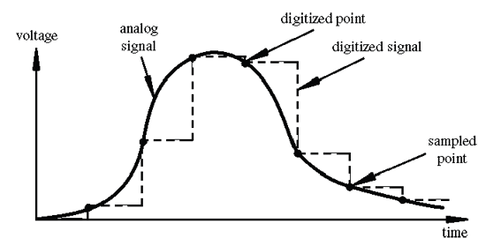 Image credit: Tod Kurt
In a digital device, we discretize the input signal range (i.e., -VRef to +VRef) into different voltage
levels or intervals called states. The number of states is the resolution of the digital
representation. Common resolution values range from 256 states (i.e., stored in 8 bits) to 4,294,967,296
states (i.e., stored in 32 bits). The PIC24 offers either 10 bits (the default) or 12 bits to store the state.
Assuming the 10 bit default state representation with -VRef=0 and +VRef=3.3, the smallest voltage change
that can be measured is (3.3-0)/210=3.3/1024 = 3.2mV. These calculations are expressed in your
text as follows:

The translation of analog voltage values into different states is called Analog-to-Digital
Conversion or ADC. For a one bit representation (i.e., a representation using just one state)
the process might be accomplished as follows:
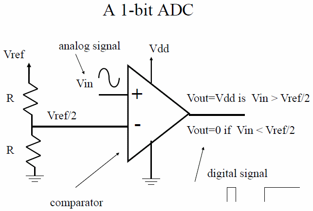
A 2 bit representation (i.e., 2 states, D1 D0) can be created by extending this "flash" conversion
process as depicted below.
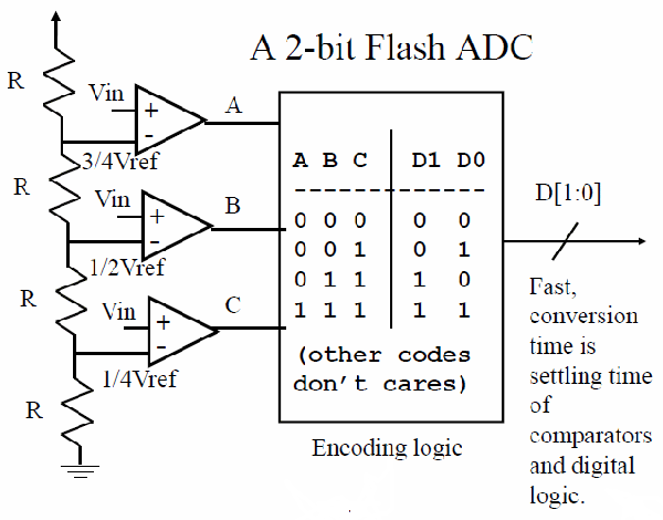
Of course such a conversion would be quick (1 clock cycle), but very costly from a hardware perspective
(e.g., consider the number of comparators needed for 10 bits---210-1 comparators). An alternative
approach is that of "successive approximation."
At the start of the successive approximation conversion, the input signal is placed in the hold mode, and the internal DAC Voltage (VDAC) is set to mid-scale(i.e., Vref/2). A comparator determines whether the input voltage is above or below the VDAC, and the result (bit 1, the most significant bit of the conversion) is stored in the successive approximation register. The VDAC is then set either to ¼ scale or ¾ scale (depending on the value of bit 1), and compared to the input signal to set bit 2 of the conversion. The result is stored in the register, and the process continues until all of the bits of the digital representation have been determined. The full conversion takes N (i.e., the number of bits set) clock cycles. Your text represents the process as follows, where TAD refers to clock cycles:
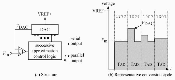
Although slower than "flash" ADC, "successive approximation" is less expensive and provides high precision. It is the ADC process of choice for many applications including the PIC24.
The built-in ADC features of the PIC24 are as follows:
- Successive approximation
- 10-bit (default) or 12-bit resolution
- Reference voltage can be Vdd (3.3 V) or separate voltage (min AVSS + 2.7 V)
- Multiple input (more than one input channel)
- Clock source for ADC is either a divided Fosc, or and internally generated clock. The ADC clock period
(TAD) cannot be less than 76 ns for 10-bit mode, or 118 ns for 12-bit mode. The internally generated clock has a period of ~ 250 ns (~ 4 MHz).
Now, let's use all of this good stuff. Begin by creating the analog input circuit depicted below on your
breadboard.
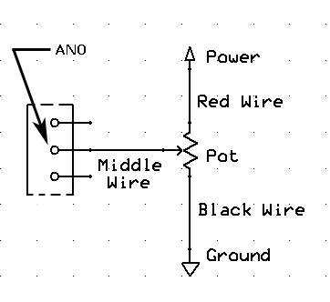
Open chap11/adc_test.mcp from the the example code archive. Study the code, and then watch this
silent video tutorial to better understand the program and its output. Compile and run adc_test.c and verify that the output is as expected.
| Show your instructor your program in action. |
|
Part 3: Analog Input and Digital Output
The amplifier and speaker that you used in
Lab 12 should still be
connected to pin RB14. In the next program, you will use analog input on pin AN0 to control digital output
on pin RB14. Begin by opening chap11/adc_test.mcp, if it is not already open. Create a new
theremin.mcp project by saving the project with that name. Remove the file adc_test.c
from the project and in its place add
theremin.c.
Open theremin.c and study the code. Compile and run the program. Use the pot to adjust the input
voltage. Is the behavior what you expected?
| Show your instructor your new theremin program in action. |
|
Part 4: Making A Theremin
The tone produced by a theremin changes in response to the proximity of the hands of its player---that's not what we have right now. Create a better approximation to a theremin by replacing the potentiometer circuit with the one shown below. In the circuit below, you are using a photoresistor in a voltage divider and sensing the voltage between the two resistive elements. The resistance of a photoresistor changes in response to the light hitting its surface. The voltage at the midpoint of the voltage divider therefore changes as the light hitting the photoresistor changes.
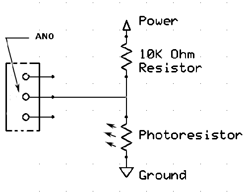
Once you've created the theremin circuit, run theremin.mcp and play with your new instrument.
| Demonstrate your theremin for your instructor. |
|


