CSCI 255 Lab
Lab 9 -- PIC24 Control of Switches and LEDs
(This lab was inspired by a laboratory exercise presented in ECE3724: Microprocessors developed by Jones, Reese and Bruce and offered at Mississippi State University.)
Part 0: Overview & Review
In this lab, you will implement switch and LED I/O using the PIC24. You will learn to compile C programs in MPLAB and transfer the executable forms of those programs to the PIC24 using the "bully bootloader" developed at Mississippi State University. The programs that we'll be working with are located in the example code archive that you downloaded to a USB memory stick in Lab 6. IF YOU HAVE FORGOTTEN YOUR USB DRIVE, you can still proceed by mapping your home directory to a Window's drive and then downloading the code archive again. Downloading the code archive to your home directory will take a VERY LONG TIME, so don't do this unless it's absolutely necessary.
Mapping your home directory and downloading the code archive
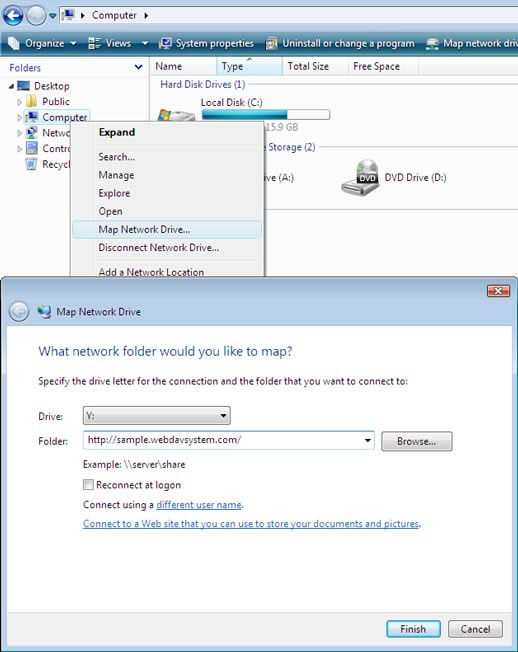
You can map any directory (in this case, we'll choose your home directory) to an external Window's drive using this procedure:
- Open Windows Explorer by right-clicking on the
Start Icon at the lower left of the display.
- Right-click on the
Computer icon located on the left-hand-side of the Explorer Window, and select Map Network Drive... from the pull-down menu.
- Select drive H: and designate
\\horseshoe\users\Your_Account_Name as the folder to be mapped. This should complete the drive mapping operation.
- Download the example code library. Unzip the archive into your
Documents (or My Documents) sub-directory; this will be the default choice. The download will take a VERY LONG TIME. Proceed to Building your PIC24 development board while you wait for the download to complete.
Building your PIC24 development board
Before you can begin this activity, you must have a fully functional PIC24 development board constructed as described in Lab 8. So... if you haven't completed your development board, do that first by following the instructions provided in Lab 8 and asking your lab instructor for help if you need it.
Part 1: Downloading a Program using the Bootloader
The "bully" bootloader has already been installed on your PIC24 processor and the lab computers. If you are interested in doing this at home, all of the software used in the lab is freely available, but the bootloader firmware must be installed on your PIC24 processor using something like the "PICkit 2."
Follow the steps below to load a program on to your PIC24.
Plug your USB-to-Serial cable into the 6-pin header on your board and into your PC. Position the power switch on the board to receive power from the USB connection.
-
Start the bully bootloader. You'll find it on the local C: drive in a folder entitled, Program Files (x86)/Bully Bootloader. The file name is winbootdr. In the bootloader window, select the COM port for the USB-to-Serial cable connection. If you do not know the COM port number, then use the Device Manager under Control Panel -> System -> Hardware -> Device Manager to see the serial ports (and other hardware) on your PC. Double-click on Ports, and note which port is labeled as a "USB serial port;" that's the COM port number to specify in the bully bootloader. Select the 57600 baud rate in the bootloader window, and click the OpenCom checkbox to open the port.
-
Start MPLAB. If you have forgotten your USB memory stick then you'll need to follow the instructions for mapping your home directory to a network drive and downloading the PIC24 example code archive provided above, before you proceed. Open the project chap8/echo.mcp in the example code archive (note: you must start MPLAB first, then open the project file – do not open the project file by double-clicking on it since it does not have a workspace file with it).
-
Add the following line of code to echo.c at the position indicated. This matches the baud rate specified for the bully bootloader above.
-
Under the MPLAB Configure menu option, select Select Device... and designate PIC24HJ32GP202 as the appropriate device in the drop-down device list. Select OK at the bottom of the window.
-
Use the Build All option under the Project menu to compile the echo.mcp project with the C compiler installed as part of MPLAB. If your compile is not successful, ask your instructor for help.
-
This project reads a character from the serial port, increments it, and echoes it back (so ‘1’ is echoed as ‘2’, ‘a’ as ‘b’, etc.). Use the HexFile button in the bootloader to browse to the echo.hex in your example code archive; this is the file produced during compilation.
-
Turn off power to your PIC24 processor, then turn it back on again. Click the Program button in the bootloader before 2 seconds have lapsed in order to download the hex program to the PIC24. You should see some text appear in the lower window indicating that the program is downloading.
-
Test the echo.c program functionality by using the Send button to send some text to the PIC24. You should see it echoed back, with the characters incremented by 1.
-
Modify the echo.c program to increment the character by 2 instead of by 1. Verify this operation.
| Show your instructor the modified echo program in action along with the source code. |
|
Part 2: LEDs and Switches
Flashing an LED
Begin your investigation of switch and LED I/O with the ledflash project from chapter 8 of the example code library. Select Close from the Project pull-down menu to close the echo project. Use
Open from the Project pull-down menu to open chap8/ledflash.mcp. Study the code in ledflash.c and then view this silent tutorial to better understand the statements that you see.
Before compiling
ledflash.c, add the statement below to change the baud rate:
#define DEFAULT_BAUDRATE 57600
Compile the program and use the bully bootloader to transfer it to the PIC24.
Because your processor has already been programmed to blink the LED on pin 15, it should be difficult to detect any difference in its behavior. Modify the blink rate specified in ledflash.c, and transfer it again. Verify that you can see a new behavior.
Add a Switch and an LED
Close the ledflash project and open
chap8/ledtoggle_nofsm.mcp. You need to add the baud rate command specified above, but this time it must be added to a header file(i.e., .h file). The specific file is pic24_libconfig.h. Unfortunately, that file is not visible in the ledtoggle_nofsm project view created in MPLAB. Open Windows Explorer and navigate to the include directory in the example code archive. Edit pic24_libconfig.h so that it reads as shown below.
After completing the edit above, open ledtoggle_nofsm.c in MPLAB, and study the code. Identify the hardware configuration expected by the program. Create that configuration on your breadboard and then run the program on your PIC24. Verify the expected performance and then shown your instructor.
| Show your instructor the ledtoggle_nofsm program in action. |
|