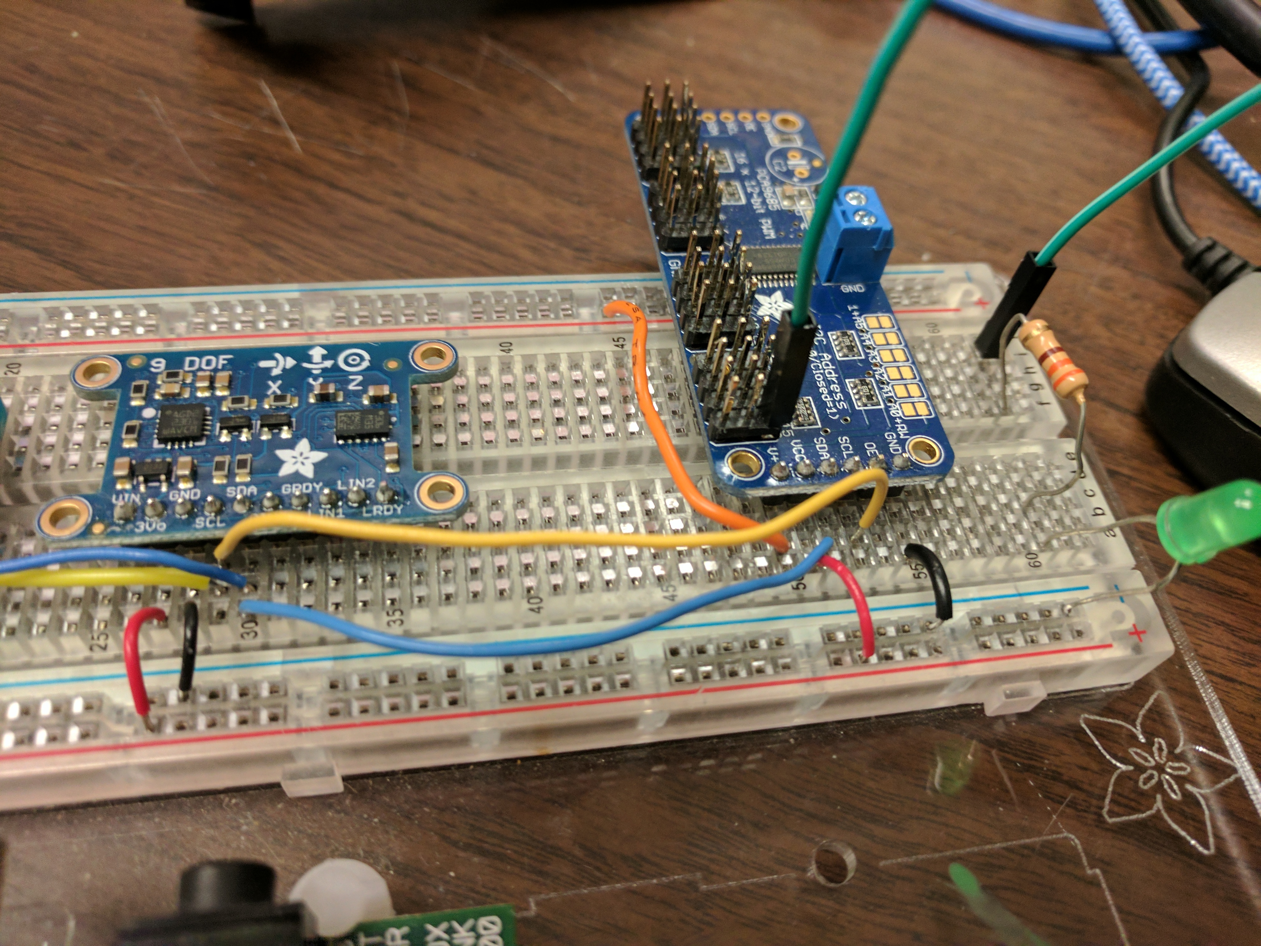
Wiring up the Pi
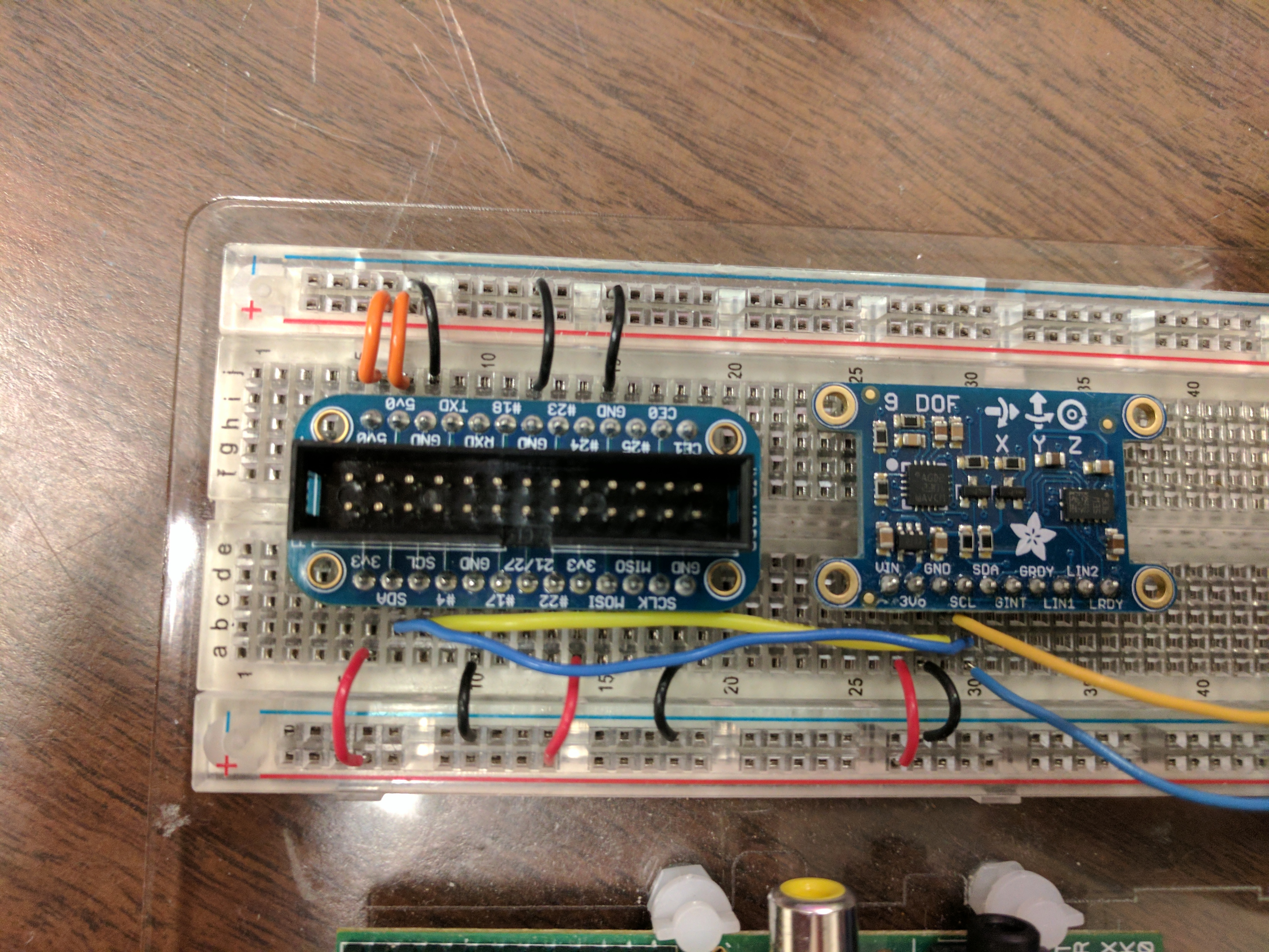
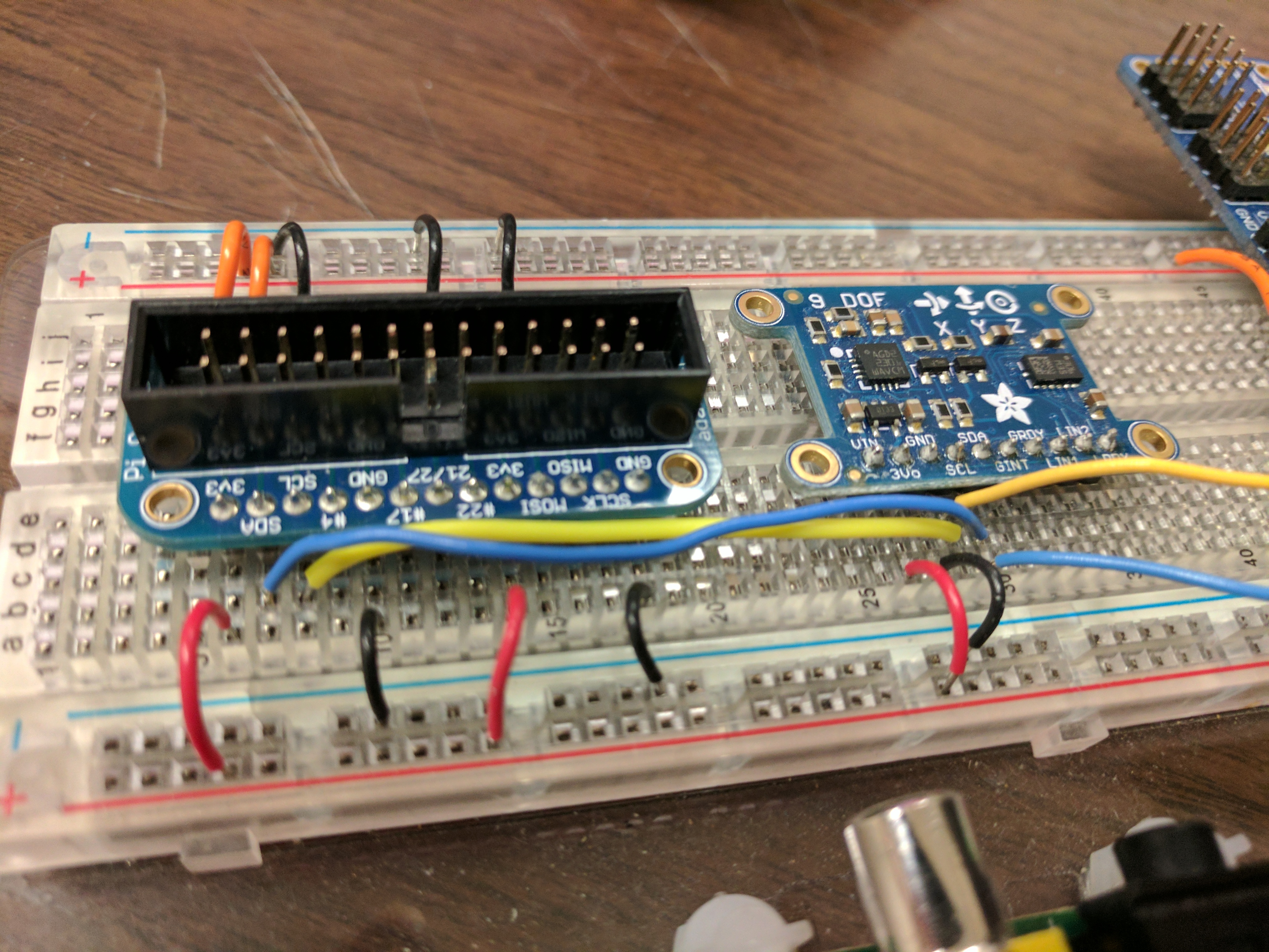
Follow the pictures carefully. It isn’t that hard.
- 3.3v side
— Note the I2C bus wiring on
SDAandSCL - 3.3v side
— Note the I2C bus wiring on
SDAandSCL - 5.0v side — The 5v connections are used to power servos etc.
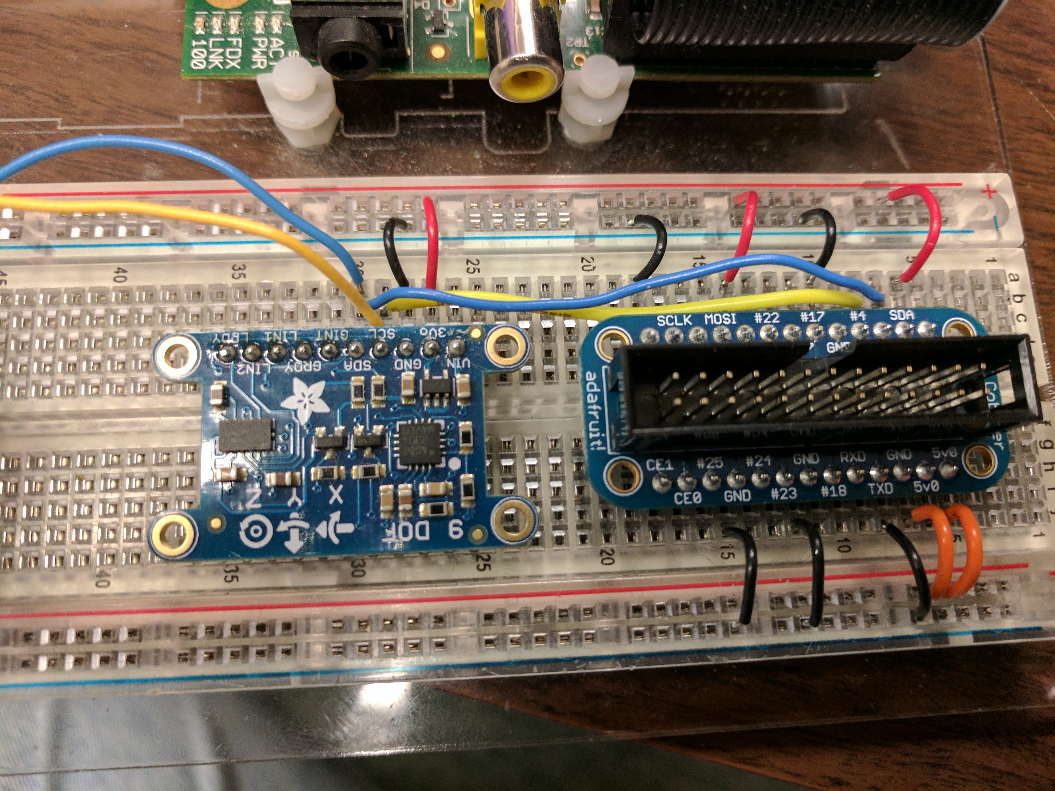
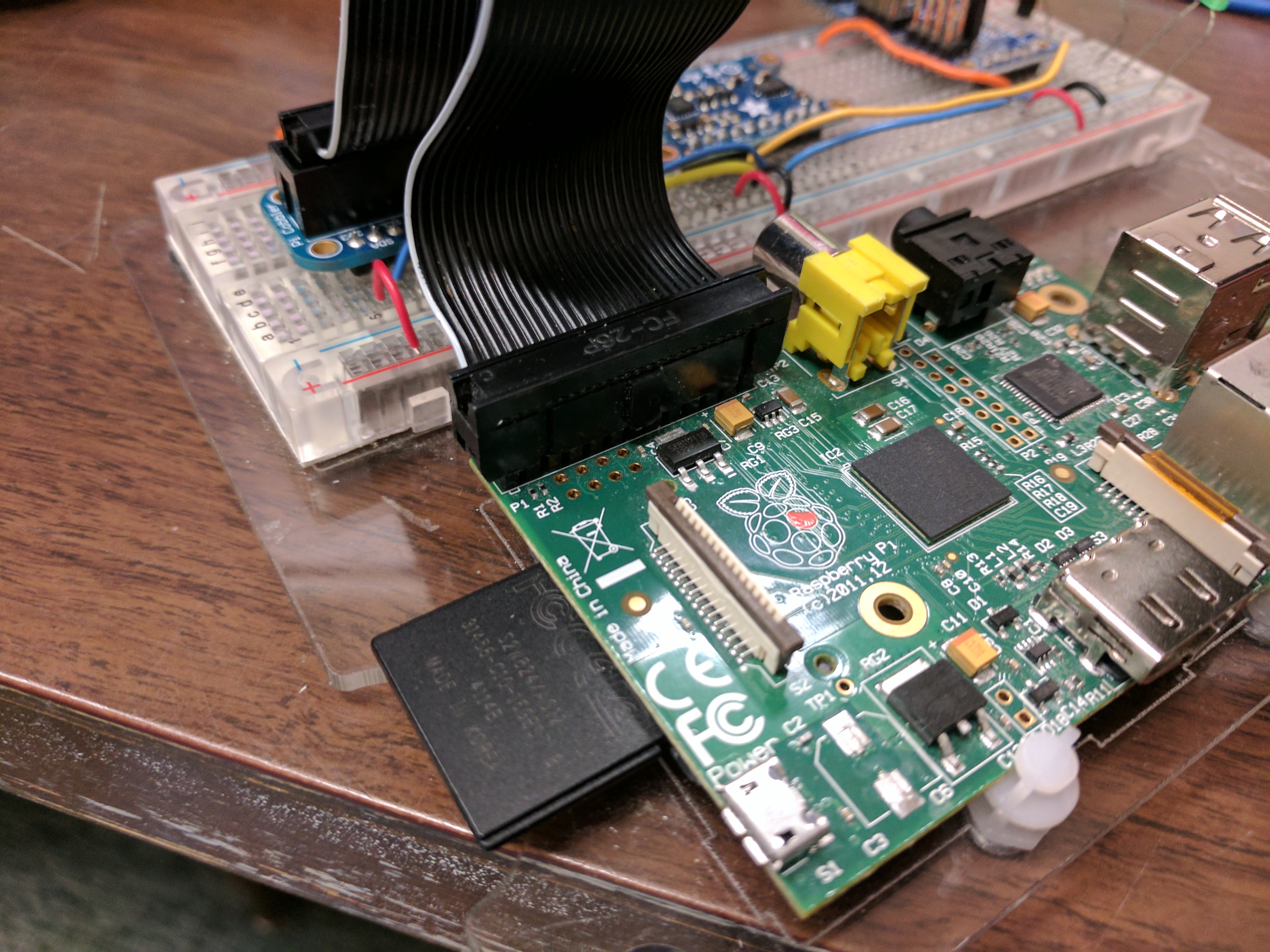
- Pi Cobbler — Note the position of the white line
- PCA9683 connection —
The 5V line connects to
V+
UNCA CSCI references
- Last week’s GPIO lab — Useful information about setting up the Pi
- Final lab of Fall 2016 CSCI 178 — Connecting to the Pi through the web
- Setting up Pi I2C in CSCI 178 — How to monitor sensor over the net
- Hopefully working link for getting the orientation of uncacsci-pi-j.cs.unca.edu in JSON
Checking your wiring
id
i2cdetect -y 1
You should see devices at 19 (LSM303 accelerometer),
1e (LSM303 magnetometer)
and 40 (PCA9685).
Setting up the libraries
This should not be necessary because the libraries should have been installed in CSCI 178. If they are missing, try the following or look at last term’s CSCI 178 lab. (You can just proceed ahead until you encounter a problem.)
git clone https://github.com/adafruit/Adafruit_Python_LSM303
sudo python Adafruit_Python_LSM303/setup.py install
git clone https://github.com/adafruit/Adafruit_Python_PCA9685
sudo python Adafruit_Python_PCA9685/setup.py install
Copying the examples
Adafruit libraries come with nice test programs. However, you meed to give them distinct names. Also, make them executable using chmod.
cp Adafruit_Python_PCA9685/examples/simpletest.py ~/pwm.py
cp Adafruit_Python_LSM303/examples/simpletest.py ~/9dof.py
chmod a+x pwm.py
chmod a+x 9dof.py
Running the examples
And accelerating experience
Take a look at 9dof.py. It’s pretty simple. I just prints the orientation.
Start 9dof.py, by typing ./9dof.py, and move your Pi. You see the numbers change. Try to figure out what the X, Y and Z values mean. (Hint: Look on the 9DOF device.)
Now modify 9dof.py to print in g-forces. You can do this by dividing the X, Y, and Z values by 1024.
Turning the lights on and off
You will need to modify pwn.py to use the right pin number.
(Right now it is using pin 0.)
Because the program is be run with a servo, while are in use in EGM 180 right now, the results will not be very interesting.
Try change the range of teh pulse from 150 and 600 to 1000 and 4000. Better yet try a loop that starts
with something like the following:
for p in range(pulse_min, pulse_max, 50):
You’ll need to define pulse_min and pulse_max.
Getting the sensos to work together
If you are ready for a challenge, merge pwm.py and 9dof.py into a single
program that turns on the LED when the Raspberry Pi is stilted, that is, when the Z-axis acceleration
is less that 0.9g.