This lab gives you a head start on and upcoming homework.
In the lab and homework, You will take a FSM from a diagram to an
implementation in logisim.
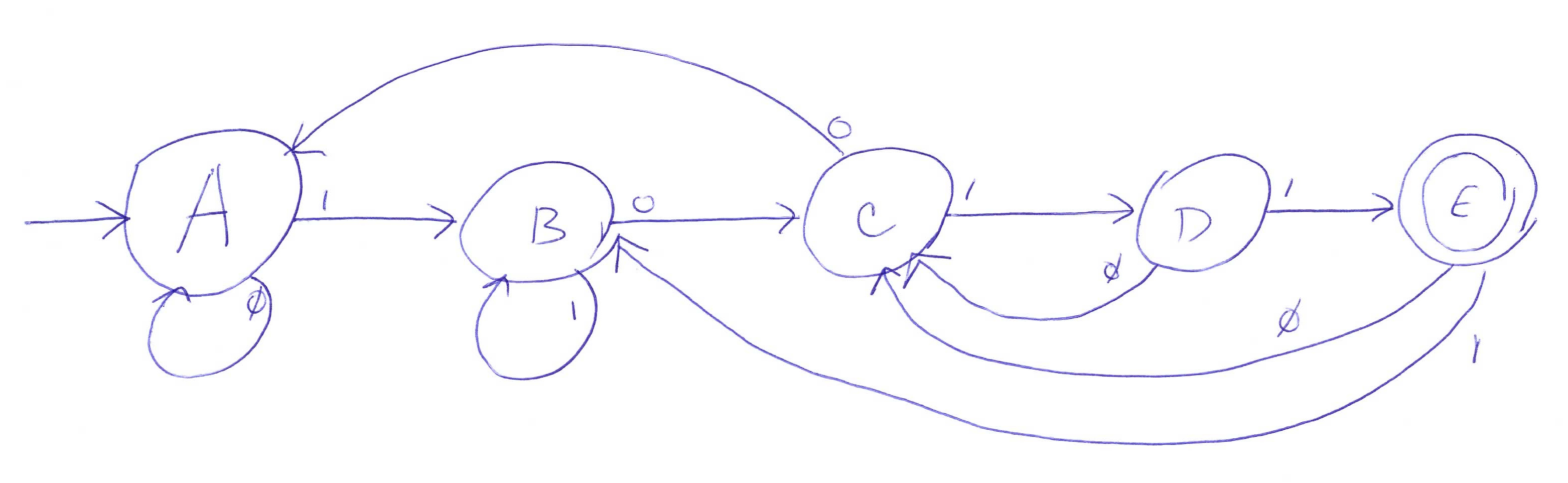
The FSM has one input and one output. It will output a 1
only when the preceding four input values are 1011.
Here’s a FSM diagram.
Task 1 — The table specification
In this part of the lab assignment, you will create three tables describing the FSM. I strongly suggest your start with the spreadsheet specification of the Nabs FSM that we used in class and make the necessary modifications. This spreadsheet already contains the three tables.
- The state transistion table in “English”
- The binary encoding of the FSM states. Because this FSM has five states, you will need three bits to encode the states.
- The state transistion table as a truth table. You will need to modify the truth table because the states of this FSM are implemented with three, rather than two, bits and the inputs and outputs of this FSM are one, rather than two, bits.
Task 2 — The circuit implementation
Now implement your FSM as the circuit level using
logisim.
Start with the
solution
to the Fall 2015 homework discussed in class.
Delete everything but the subcircuit
HW5 solution and
then try to make a minimum number of alterations.