In this lab, you are going to be given an SystemVerilog “include” file and the outlines of two SystemVerilog modules, one that will test the other. Each will contain comments that you should complete in the lab.
This lab is also a graded homework assignment. If you have your modules working by the end of the lab, just upload them to Moodle as Homework 8. Otherwise, you will need to work on them as you would any other homework assignment.
The big picture
You are going to program a countdown module. The countdown module has three commands that can be performed in a clock cycle.
- The
LOADcommand copies an input value, with a size determined byparameterDATA_WIDTH, into a register of the countdown module. - The
DOWNcommand decrements the register until it reaches the value 0. - The
HOLDcommand does nothing. It just holds on to the present value in the register.
The countdown has a single output, atZero, which is 1
only when the register has the value zero.
Creating a project
Start by creating a SystemVerilog project called
countdown in a new directory
with three initially empty SystemVerilog programs with the
names given below.
- count_defines.sv
- countdown.sv
- countdownTB.sv
Oddly enough, you should be able to successfully compile these files even though they contain nothing.
The “include”
SystemVerilog has an include mechanism similar to C”s
and, consequently,
far less useful than the import mechanism of Java.
The entire contents of
count_defines.sv will be the following
definition of the bit fields for the three commands. This use of the
enum is similar to that of Java and C.
typedef enum logic [1:0] {
  LOAD   = 2'b00,
  DOWN   = 2'b01,
  HOLD   = 2'b10
} commandType ;
Copy this typedef into
count_defines.sv.
`include "count_defines.sv"
This directive effectively inserts
count_defines.sv into your program.
It is similar to the #include directive of
C and C++.
Be sure you can still compile this project that does nothing.
Working on the countdown module
Parameters, inputs and outputs
Insert the following as the body of countdown.sv.
module countdown
  // Define a parameter DATA_WIDTH here.
  // Give it the default size of 8.
  // This is the size of the register of the countdown module
  #()

  // Define inputs and outputs for your module.
  // Be sure to use the suggested names
  (
  // Here are the four inputs
  // 1:  A clock input:                            clk

  // 2:  A reset input:                            reset

  // 3:  A commandType, from the include, input:   action

  // 4:  A input with DATA_WIDTH bits:             value

  // And here is the single input
  //     An output for the result:                 atZero

  ) ;

endmodule
You should still be able to compile your project.
Edit countdown.sv to insert the four input and one output variable definitions mentioned in the comments. This will be similar to, but simpler than, the module header used in Homework 6. Be sure to use the suggested names. It will make it easier to follow the next part of the assignment.
Be very careful that you spell the variable names correctly.
If you do not declare a variable in SystemVerilog, it will be treated as
an implicitly declared one-bit logic variable.
This means that misspelled variables are often ignored by the
compiler.
This in one way SystemVerilog like FORTRAN IV.
Also, your program might just look a little better if you delete those fill-in-the-blank comments.
Make sure it still compiles.
Completing the module
Now you must make the module do its job.
Start by inserting the following comments
into the countdown module.
You should be able to figure out where the comments go.
  // Add a single declaration here for the count down register.
  // This register must hold DATA_WIDTH bits.
  // Call your variable countValue


  // Now add an always_ff block that is triggered on the
  //   positive edge of clk or any change of reset
  // The block performs the following actions
  // If reset is 1
  //   set countValue to 0

  // If reset is 0 and action is LOAD
  //   set countValue to value (load it!)

  // If reset is 0 and action is DOWN and countValue is more than 0
  //   decrement countValue

  // Finally, add a continuous assignment statement to set atZero to 1
  //   when countValue is zero.
Use the non-blocking assignment (<=) inside
the always_ff block.
The continuous assignment statement is the one which starts
with the keyword assign.
Whenever you encounter a situation where you would have to
use braces ({ … }) in Java,
JavaScript, C, or C++, you must use the much more wordy
begin … end in SystemVerilog.
Yep. Compile it.
Testing in the simulator
Start up the simulator and test your module.
When you see the Start Simulation window,
you select the countdown module, which should
also be known as the work.countdown design unit.
Take a very careful look at the variables listed in the
Objects window.
It should look something like the following picture:
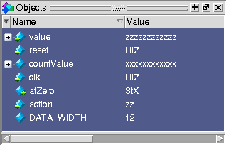
Your Objects window
doesn’t have match this one exactly.
In particular, you may have chosen a different default for
DATA_WIDTH.
But be on the outlook for pairs of similarly named variables, such
as atZero and atzero.
These will cause you much trouble.
You’ll have to use force to set the input values and
run to execute your program for a few milliseconds.
I’ve noticed a few students using a one-line
command consisting of four vsim commands
to clock the circuit.
Combined with the up-arrow key to recall previous commands, this
really speeds up manual simulation.
You can also use the names defined in
count_defines.sv in your commands.
Here’s an example of few useful simulator commands.
force value 'd42
force action LOAD
force clk 1 ; run ; force clk 0 ; run
force action DOWN
force clk 1 ; run ; force clk 0 ; run
Load the countdown module with 13 and count down to zero.
Remember to use the up-arrow key to recall previous in the simulator.
Finally a test bench
We now turn our attention to countdownTB.sv.
The module header
The module header is easy. Just use the following.
module countdownTB
      () ;

endmodule
Adding the dut — device-under-test
Instantiation seems to be a problem in courses CSCI N where 181 ≤ N < 400, so let’s get some more practice!
First add the following comments into your module.
  // The countdown module has five connections: 4 input and 1 output.
  // In this program, the countdown module must be instantiated using the
  //   following five variables to use code provide with the lab.
  // Declare these variables below.

  // clk, a 1-bit logic value

  // reset, a 1-bit logic value

  // command, a value of type commandType

  // limit, an 8-bit logic value

  // outData, a 1-bit logic value

  // Now instantiate a countdown module using the variables declared above.
  // The width of the instantiated module should be 8.
  // The name of the instantiated module should be "dut".
  // This is a single statement in SystemVerilog!
  // It is also like an internal method call in Java.
Again, this is similar to but simpler than what was needed for Homework 6.
If you wish you can add this compiler directive at the beginning of your program. It will do some checking for misspelled words.
`default_nettype none
Once again compile your module; but, to make sure the parameters and input and output variables match, you should also start up the simulator even though you will do nothing with it.
Adding a task
A task is similar to a function, but it can use
delays. Add the following humongous task into your
testbench.
  task countToN(int unsigned N) ;
    int i ;
    limit = N ;
    $display("Counting from %d", limit) ;
    command = LOAD ;
    #100 clk = 0 ;
    #100 clk = 1 ;
    command = DOWN ;
    for (i=0; i<limit; ++i)
      begin
        $display("Output at clock cycle %d after load: %b", i, outData) ;
        #100 clk = 0 ;
        #100 clk = 1 ;
      end
    for (i=limit; i<limit+10; ++i)
      begin
        $display("Output at clock cycle %d after load: %b", i, outData) ;
        #100 clk = 0 ;
        #100 clk = 1 ;
      end
  endtask
Better use a compile to make sure you pasted the cut correctly.
Using the task
The only thing you need now is an initial block to call
the codeToN task.
Insert the following comments and add code to do what they say.
  // Add an initial block to perform the following activities
  // First,     Set reset and clk to initialize the countdown module
  // Second,    Call countToN to test the module
  // Third,     $stop ;
Compile and simulate your testbench.
Start up the simulator and test your module.
In the Start Simulation window,
select the countdownTD module, which is
also known as the work.countdownTD design unit.
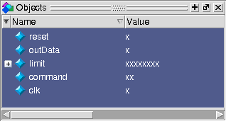
If you run it for a million units, it should display 0 for thirty clock cycles and 1 for ten clock cycles.
By the way, your
Objects window
should look something like this before you start the simulation.
If feeling ambitious
If you want some more to do, you can try modify countToN
so that it uses an external clock.
This requires adding something like the following always
block to the testbench.
      always
      begin
        #100 clk = 0 ;
        #100 clk = 1 ;
      end
Then you need to remove the delays from the countToN task and
replace them with a block on the clock.
This really can reduce the size of the testbench code by removing
a lot of those delay statements.
Here is an example loop with a block on a clock from a testbench used to test Homework 6.
        while (i<1000 && !ready)
        begin
          @(negedge clk)
          ++i ;
        end