This assignment must be uploaded with the filename ancienttimes.sv by 11:00 PM on 16 March to the homework 6 moodle page.
Getting ready
There is method of multiplication that goes by many names, one being Ethiopian multiplication, that has been used for millennia. In this method, one number is continually divided by two while the other is doubled. You can see an explanation of this in the Cut the Knot description for Peasant Multiplication.
Oddly enough, because these ancient methods are passed on division and multiplication by two, they work fairly well for multiplying integers in a computers.
The task
Your assignment is to write a reverse engineer a circuit based on
peasant multiplication and write a program to mimic it
in SystemVerilog.
You should call your multiplier ancienttimes and it
should have the following header.
module ancienttimes
     #(parameter DATA_WIDTH = 12)
      (input    logic                    clk,
       input    logic                    reset,
       input    logic                    start,
       input    logic [DATA_WIDTH-1:0]   p,
       input    logic [DATA_WIDTH-1:0]   q,
       output   logic [2*DATA_WIDTH-1:0] result,
       output   logic                    ready) ;
What it should do
The circuit to be mimiced has been “implemented” in
Logisim, the
circuit simulation tool used in
CSCI 255.
I suggest you
download the circuit
and test it out in
Logisim.
Here is a picture of the circuit.
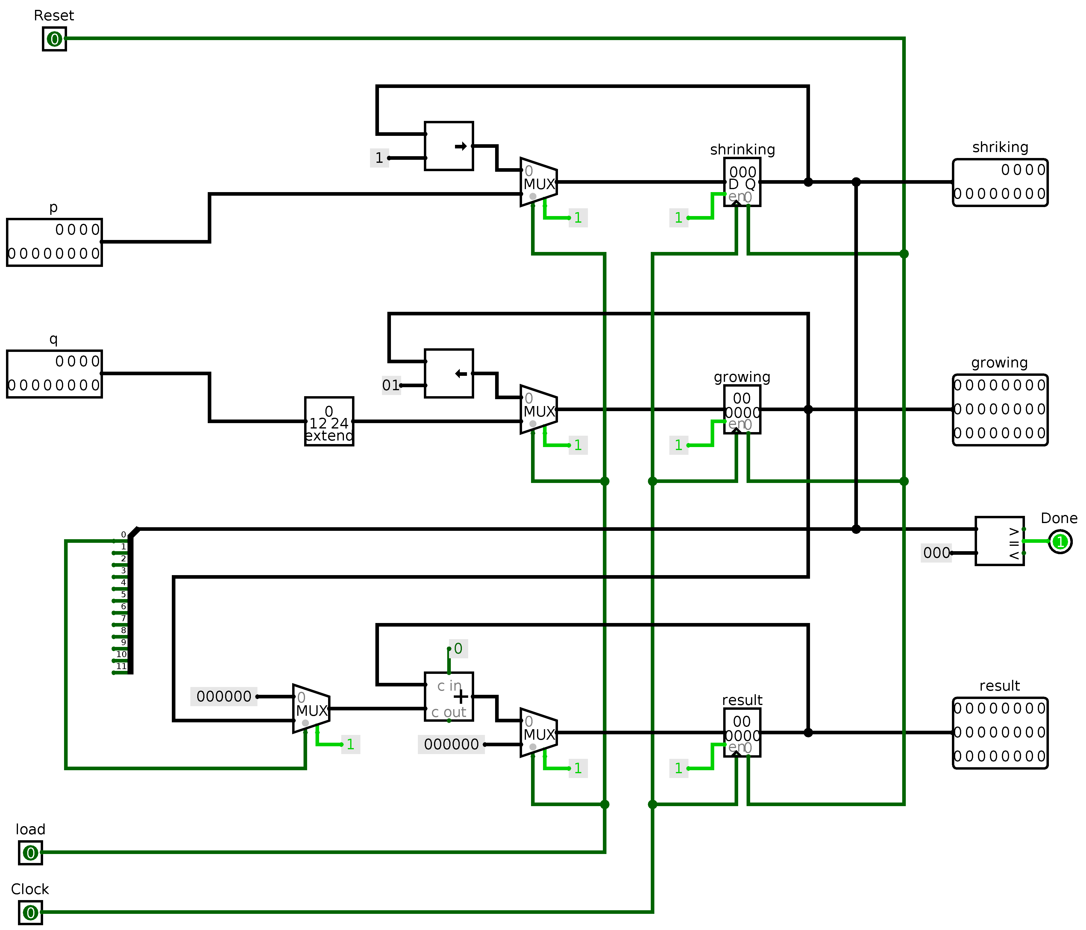
Follow these steps to see what it does.
- All the circuit inputs are on the left side. Be sure that all the inputs are initially zero. (This should be the case.)
- Assert and the deassert the
resetinput to initialize the circuit. This should change nothing. - Turn the clock on and off a few times. Nothing should change.
- Put interesting values on the
pandqinput pins. I suggest 000000101010 (42) forpand 000011111111 (255) forq. Then assertloadfor one up-and-down clock cycle.pwill be loaded intoshrinking,qwill be loaded intogrowinganddonewill be zero. -
You can go through a few more clock cycles with
loadasserted. Although nothing appears to happen, the circuit is loading values frompandqeach cycle. Be sure that each every clock cycle ends withclkbeing 0. -
Let’s do an multiplication. Clear
loadto 0. Now slowly clock the circuit. You will see the bits ofshrinkingmove to the left and the bits ofgrowingmove to the right. Theresultwill be incremented just as it was for the ancients. -
At some point,
shrinkingwill reach 0 anddonewill turn on indicating that the multiplication has completed The result should be 000000000010100111010110 (10710). - Now that
doneis asserted, you can load another pair of inputs and try again.
If you missed using Logisim in the prerequisite course, you may want to look at introductory labs from CSCI 255 or ECE 109. You can download Logisim from its web site. The program is written in Java and, consequently, runs on Linux, Mac OS, and Windows.
What you do
Your SystemVerilog module should closely mimic the provided circuit. Your module does not just receive a value and return it, like the many implementations found on the net in Java or C or Python or even VBA. Your SystemVerilog module must implement that circuit by performing clocked steps where at most one addition is done. Like the attached Logisim circuit, your SystemVerilog module should use the positive edge of the clock signal.
Most of the variables needed in ancienttimes
are provided are already parameters in the module header.
However, each register in the circuit requires two values, one for
the present state and the other for the next state.
This means you need to add five internal variables.
It is less than forty additional lines of SystemVerilog.