LOW. Otherwise, the
input was HIGH.
This is a rather crude example of the single pole single throw switch that you often flip to turn lights off and on at home.
This week we're going to spend a little time learning more about Arduino inputs and outputs and how to use our breadboards.
You really don't need to know a lot about electricity for this course, but it does help to know Ohm's law, V = I*R. V is electrical potential as measured in volts. In this course, this is almost always 5 volts. I is current, measured in amps. It represents how many electrons are following down the wire. It this gets too big, our circuits may be damaged. R is resistance, measured in ohm's. This number represents how easily the wire (or whatever) allows these electrons to pass. Generally resistance will be marked on components using the resistor code.
We've been using 330 Ω resistors to limit current to our light-emitting diodes. The LED is an unusual device. It really wants 2 volts out of our 5. This leaves 3 volts for the I*R part of Ohm's law. When a 330 Ω resistor is placed in series with an LED, the LED recieves with about .01 amps (3 Ω / 3 V) of current. This gives a bright glow that is well below the 50 mA (or so) that the Arduino output pins can safely produce.
Take a look about one of the many current limiting resistor calculators available on the Internet before reading on.
In the previous lab, we made crude switches by physically moving a
wire to touch one leg of a resistor.
The resistor was electrically connected between 5 V and an
Arduino input port. Our "switch" wire was grounded. When the
switch wire touched
the resistor leg connected to the Arduino input, the
input was set to LOW. Otherwise, the
input was HIGH.
This is a rather crude example
of the single pole single throw switch
that you often flip to turn lights off and on at home.
That more complicated home light switch, the one where you can change
the lights
from two locations, is an example of a
single pole double throw switch. If you had used one of these,
you wouldn't have needed a resistor.
We're using solderless breadboards to make connections to the
Arduino board. To maintain a little consistency we are going to
try to get everyone using "half size" breadboards. (Those little
blue breadboards were much too "mini".)
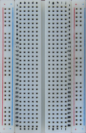
On each side of the breadboard, there are two columns of thirty holes. That's 120 holes partitioned into four columns. These columns are called bus strips and are intended to distribute ground and supply voltage (5 V) throughout the board. All thirty holes of each column are electrically connected. You should set up your board so that the bus strip next to the red line carries 5 V and the bus strip next to the blue line carries ground (0 V).
The remaining 300 holes are connected into sixty five-hole terminal strips. Notice the thirty rows, numbered from 1 to 30, and ten columns, lettered from 'a' to 'j'. In each row there are two sets of five connected holes. Each set is on one side of that big notch running down the middle of the board.
If you want to see some really big prototype circuits created with breadboards check out one for the Intel 8080 and another for the Motorola 68000. You can also try out an Java applet that simulates breadboards.
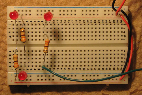
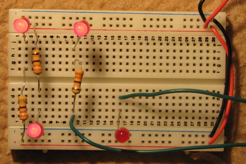
I suggest you initially wire your breadboard as shown below.
It is always a good idea to reserve one wire color for ground, black in
this case, and another for 5 V, red in this case.
If you know a wire will always be 5 V, make it red.
If you know a wire will always be ground, make it black.
Then, never connect red and black.

This setup has 5 V and 0 V running down the appropriate bus strips
and
has LED's connected between the 5 V and ground bus strips on opposite sides
of the board. If the LED's light up, the breadbroad is appropriately powered.
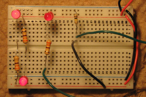
Now add an LED and 330 Ω resistor, connected in series, to your breadboard
just like you did last week. Use a wire than isn't red or black to
connect to a digital output pin other than 13
of your Arduino board. Just like last week,
run a little program to flash the LED.
You can even use the program shown below.
// Flash LED attached to pin 3

int ledPin   = 3 ;
int ledOn    = 1 ;

void setup()
{
  pinMode(ledPin, OUTPUT) ;
}


void loop()
{
  if (ledOn)
    digitalWrite(ledPin, HIGH) ;
  else
    digitalWrite(ledPin, LOW) ;
  delay(1000) ;
  ledOn = 1 - ledOn ;
}
Some of you may be remembering that you once lit an LED without a resistor. Yep, you can do that, but only with Pin 13. That's because there is 1k Ω (1000 Ω) resistor built into the Arduino board through which the output of Pin 13 passes. Don't connect any other Arduino pin to an LED without a current limiting resistor.
Wire your breadboard with an LED directly connected to Pin 13.
Now write an Arduino program to flash both LED's but make sure that exactly one LED is on at a time.
Remove that LED connected to Pin 13 before it gets us in trouble.
Next make a switch by connecting one end of a 10k Ω resistor to 5 V.
Connect the other end to both ground (with, of course, a black wire) and an
Arduino digital port.
Right now the wire going to the Arduino is at 0 V.
However, when you pull out the
wire to ground, the wire going to the Arduino will be a 5 V.
Next, write a program that uses your switch to turn the LED off and on.
Be sure to call the pinMode function from your setup
routine to set your pins to the appropriate modes.
  pinMode(swtchPin, INPUT) ;
  pinMode(ledPin, OUTPUT) ;