18f26j10.lkr as
shown below before I could compile my project.
| time due | submission file |
|---|---|
| Monday, 7 May | in office or via email |
The assignment is to express Problem 3 of Quiz 2 (the shift register) in a C or assembly language that could be executed on a PIC processor. Turn in a carefully commented and documented program.
For my C program, I chose the PIC 18F25J10 processor. The MicroChip C compiler is only supposed to work with the PIC 18 processors and the 18F25J10 was the cheapest and (I assume) also the simplest.
I decided to use bits of PORTB for input and
bits of PORTC for output.
I used the least significant six bits of PORTC for output.
The header for my C code starts with the following definitions
that reveal my choices for the input bits.
#include <p18cxxx.h>

#define CLK  PORTBbits.RB0
#define RST  PORTBbits.RB1
#define OPT0 PORTBbits.RB2
#define OPT1 PORTBbits.RB3
I downloaded MicroChip's MPLAB IDE to simulate my design. I also downloaded the student edition of their C18 compiler to compile my code.
There are a few odd settings you need to follow to use C18 and the IDE.
I suggest you review some of the on-line information from MicroChip.
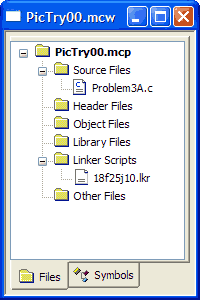
I had to set the "linker script" to 18f26j10.lkr as
shown below before I could compile my project.
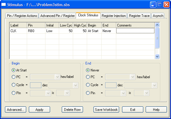
I also created a special stimulus file
for debugging my program.
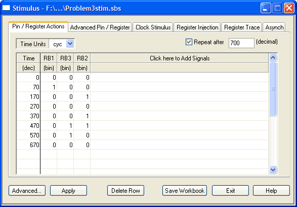
Here are the stimulus settings I use for the clock
and here is what I used for the inputs.
I chose to use the cheapest process with at least ten I/O pins
and an internal oscillator. That was the PIC 16F505.
Once the process is chosen, it's easiest to start programming by
loading in MicroChip's default template for your processor
so that your assembly program begins with a
few appropriate definitions.
I kept MicroChip's initializations except that
I set _MCLRE_OFF
because I planned to use the MCLRE pin as a regular
digital input.
	list      p=16F505            ; list directive to define processor
	#include <p16F505.inc>        ; processor specific variable definitions

	__CONFIG   _MCLRE_OFF & _CP_OFF & _WDT_OFF & _IntRC_OSC_RB4EN
I used the same pin assignments as I did for C, PORTB
for input and PORTC for output.
Here the declarations are a bit more complicated.
;***** PORTS
BCLK    EQU     0
MCLK    EQU     B'00000001'
BRST    EQU     1
MRST    EQU     B'00000010'
BOPT0   EQU     2
BOPT1   EQU     3
MOPT    EQU     B'00001100'

;***** VARIABLE DEFINITIONS
sreg	EQU     16        ;shift register
Finally, here's the small section of code I used to initialize the ports.
    ORG     0x000             ; coding begins here
    movwf   OSCCAL            ; update register with factory cal value
    movlw   B'00111111'
    tris    PORTB             ; set pins of PORTB as input
    clrw
    tris    PORTC             ; set pins of PORTC as output
    clrf    sreg              ; sreg = 0
After that there's a single loop (of 24 instructions) to run the finite state machine.