This homework is due 19 March, 2003.
In this lab we'll use an extremely simple digital logic schematic design and simulation tool to build a couple of digital circuits.
We'll be using a program called MultiMedia Logic, a Freeware program that can be downloaded for any Windows system.
As soon as you have MultiMedia Logic running, go to the Help pulldown menu and select Tutorial. Read at least the first four pages of the Tutorial before continuing with this assignment.
Two incomplete MultiMedia design files, EHMWK1A.lgi and EHMWK1B.lig, and one RAM "initialization" file, SLRAM.txt are needed for this lab. You should download both of these three files from a single Zip file and store them in a directory that you will use throughout this lab.
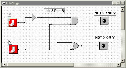
Using MultiMedia Logic, open EHMWK1A.lgi.

Go to the Simulate pulldown menu and select Run to start an interactive simulation. Now press the input switches to toggle the two inputs between 0 and 1. Convince yourself that this circuit really does compute the expressions X' Y and X' + Y.
Your job is to use deMorgan's law to modify the implementation of this circuit so that is uses only inverters and NAND gates.
Once you have modified the circuit, save it in the file ESOL1A.lgi.
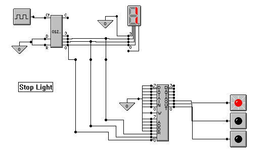
Now open and run EHMWK1B.lgi.

This circuit contains a clock in the upper-left corner that
sends a pulse to an eight-bit counter. The counter sends
three bits to a seven segment display
and to a RAM.
At the RAM, the three input bits provide the least significant
bits of an address. Three output bits of the RAM are used
to turn on LED's.
The LED's should simulate a traffic signal. However, You'll probably need to adjust the clock rate to get acceptable and interesting sequence of light changes. The reason why we are using the three middle bits of the 8-bit counter is that the clock generator of the MultiMedia Logic Simulator changes much too quickly, even at its slowest setting, on a recent ventage PC.
In this design we have effectively turned an eight-bit counter into a three-bit counter. The three-bit count is being sent into a RAM that contains the three bits needed for the LED's. Within the three-bit count; the light is green for counts zero to two, yellow for count three, and red for counts four to seven. Don't worry about how the RAM is initialized to do this. Accept it as magic.
Your job is to reimplement the RAM with combinational logic in two different ways: (1) as a decoder and a couple of NAND gates and (2) with two levels of NAND gates implementing and AND-OR solution. The effect of your RAM replacement should be to compute the following truth table in two different ways.
| Count | G | Y | R | ||
|---|---|---|---|---|---|
| 0 | 0 | 0 | 1 | 0 | 0 |
| 0 | 0 | 1 | 1 | 0 | 0 |
| 0 | 1 | 0 | 1 | 0 | 0 |
| 0 | 1 | 1 | 0 | 1 | 0 |
| 1 | 0 | 0 | 0 | 0 | 1 |
| 1 | 0 | 1 | 0 | 0 | 1 |
| 1 | 1 | 0 | 0 | 0 | 1 |
| 1 | 1 | 1 | 0 | 0 | 1 |
Store the result of the decoder implementation in the file ESOL1Bd.lgi and the result of the NAND-NAND implementation in ESOL1Bn.lgi
E-Mail the three files ESOL1A.lgi, ESOL1Bd.lgi, and ESOL1Bm.lgi to brock@cs.unca.edu.