This lab is scheduled for 20 & 21, February.
For one last week we'll use the MultiMedia Logic simulator. We'll look at the implementation of sequential systems.
Two MultiMedia Logic design files, Experiment.lgi and Start.lgi, are needed for this lab. You can download these as either a Windows self-extracting exe file or a Zip file.
Using MultiMedia Logic, open Experiment.lgi.

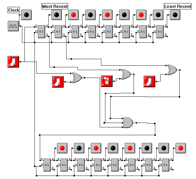
At the top and bottom of this circuit, you see two rows of eight LED's. These LED's are connected to the outputs of a shift register. Go ahead and run the circuit and press the input switch on the left-hand side of the circuit. Notice how you create a pattern of binary bits that shift to the right with time.
This circuit looks for a pattern within its input bit stream. The center collection of three switches sets the pattern. For example, if you set the three switches to the bit sequence 010 (as shown in the above example), the circuit will output an 1 when the last three inputs bits are 010.
The shift register at the bottom of the circuit displays the last eight output bits. Notice that the matched three-bit sequences are allowed to overlap. That's why the input bit sequence 0101010 has three matches.
Play with Experiment.lgi until you understand the circuit and the meaning of matching.
Start by selecting a three-bit sequence, other than 000 or 111. Your task is to build a pattern matcher for your sequence. However, there are some rules.
Be methodical.
Begin by drawing a finite state machine diagram. Your diagram should have three states, each encoding how "far" you are into the sequence of input bits. For example, one state is for when you've seen no bits of the sequence; another is for one bits; and the third for two bits.
Show your completed diagram to the lab instructor.
Write the finite state machine table in both a logical and binary format. You will need to select binary encodings of your states before writing the binary table. I suggest you use 00 for zero bits matched, 01 for one bit matched, and 10 for two bits matched.
Here's a state table for a circuit trying to match 000. We'll call the flip-flop state variables x and y, the input variable p, and the output variable o.
| x | y | p | Dx | Dy | o |
|---|---|---|---|---|---|
| 0 | 0 | 0 | 0 | 1 | 0 |
| 0 | 0 | 1 | 0 | 0 | 0 |
| 0 | 1 | 0 | 1 | 0 | 0 |
| 0 | 1 | 1 | 0 | 0 | 0 |
| 1 | 0 | 0 | 1 | 0 | 1 |
| 1 | 0 | 1 | 0 | 0 | 0 |
Show your completed table to the lab instructor.
Using your table, design a combintation circuit to drive your circuit's output and flip-flops. You can implement your combination circuit with AND's and OR's, or you can use multiplexers.
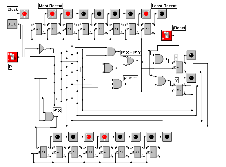
We'll implement the 000 matcher with AND's and OR's using the following equations derived from our truth table.
Open Start.lgi into the MultiMedia Logic simulator and wire in your combinational circuit. Test it when you are done.
Here's the circuit that recognizes the bit string 000.

When you are done, show the lab instructor your work.