
If you have one of these breadboards, you may want to add some of these wires, but only to the left side. We won't need to use the entire breadboard in CSCI 255.
This lab is scheduled for the week of 22-26 January.
First of all, thanks to Sally Medling, the TA for Logic Design at NCSU last semester, for generating the document from which this lab was constructed.
However, the breadboard diagrams in this lab were scanned from some ancient lab manual. There are lots of errors in the diagrams. Be sure to carefully read the text before examining the diagram. Before each faculty diagram, you will find a warning. Pay attention!
The purpose of this lab is to introduce you to breadboards, LED's, switches, and a few analog components used in digital design.
This isn't rocket science. It is a very hands-on lab. This handout only covers the basics. You'll need to listen to your lab instructor for this rest.
If you have taken an electronics course before, you should find a lab partner in need of a tutor.
The breadboard, or socket board, is an easy-to-use wiring chasis that contain lots of holes, or sockets, in which wires and components are inserted. The power and beauty of the breadboard derives from the fact that the sockets are connected by strips of metal running underneath the board. This allows you to connect components without burning your fingers with a soldering gun.
In the middle of the breadboard, you'll see a large number of small rows of five sockets. All five sockets in each row are connected to each other but not to the sockets of other rows. Along the outside of the breadboard, you'll see longer rows, or rails. All the sockets of each rail are connected. Use these rails to distribute power and ground to your circuit.
In the figure below (provided by the folks at NC State), the
connected rails and rows of a breadboard are shown. Note
that several wires have been added to circuit to make
rows W and Z into power rails and rows X and Y into ground
rails.
If you have one of these breadboards, you may want to add
some of these wires, but only to the left side. We won't
need to use the entire breadboard in CSCI 255.
By the way, Iguana Labs has a Using the bread board (socket board) tutorial with some nice pictures and useful information. If you want your own breadboard, you can get one for about $10 at Radio Shack. Batteries are not included.
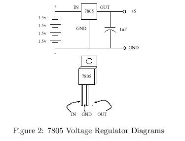
We'll be using TTL (transistor-transistor logic) chips in our labs. These chips want a nice regulated five volts. You'll use a 7805 voltage regulator receives an unregulated six (or more) volts and produces a regulated five volts. Because you're careful, you'll also use a 1µF capacitor to protect against voltage spikes on the five volt side of the circuit.
A schematic view of the voltage regulator "circuit" is shown
below:
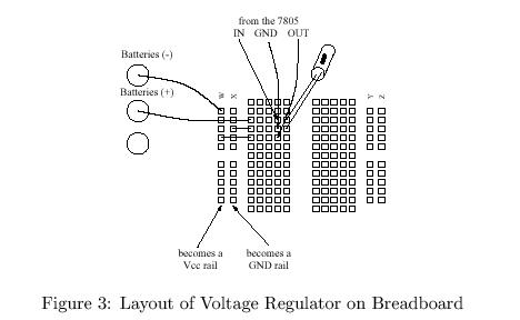
Now examine a breadboard level figure of how the
7805 and capacitor are placed.
Warning!
The wire from the negative battery terminal is drawn
incorrectly. It should be connected to row
X rather than row W.
Also, the capacitor is placed incorrectly in this diagram.
It should be placed between the GND and OUT
pins of the 7805, just as in the schematic.
Place the 7805 and capacitor on the breadboard and have your lab instructor verify your work. Be sure that your capacitor is inserted correctly.
You will view the logical outputs of your circuit on LED's. We wish for the LED to be on when the output is 1 and to be off when the output is 0. We will use a 7405, or hex inverter with open-collector outputs, for this task.
A schematic for each LED circuit is shown below:
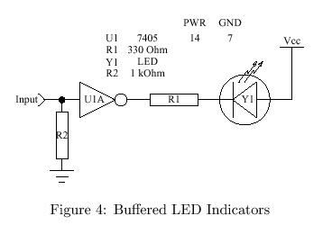
When the input to the circuit is 1, the output of the invertor
will be 0. This will sink current from the
LED. A 330Ω resistor is used to limit the current.
The 1kΩ resistor is used to protect the input.
Since the 7405 is a "hex" invertor, it has six different invertor within a single chip. Pin 7 of this chip should be connected to ground and pin 14 should be connected to power. By the way, the pins of the chip are numbered counter-clockwise starting with the notch. The pin to the left of the notch is number 1. The pin's ground connection should always be in the lower-left corner. Its power connection should always be in the upper right corner, just to the right of the notch.
The input and output connections of the chip are given in the following table:
| Input | Output |
|---|---|
| 1 | 2 |
| 3 | 4 |
| 5 | 6 |
| 9 | 8 |
| 11 | 10 |
| 13 | 12 |
Now wire up your 7405 for three outputs. The following
breadboard level diagram should help.
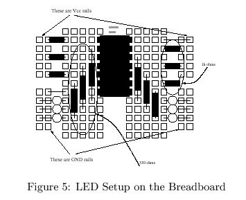
The thin lines are wires. The thick boxes are resistors.
The horizontal resistors are 1kΩ and the vertical
resistors are 330Ω.
The color bands of the 1kΩ resistor are
brown, black, and red.
The bands of the 330Ω resistor are
orange, orange, and brown.
If you don't know the resistor code,
try out Danny Goodman's JavaScript resistor calculator.
The LED's must be inserted into the breadboard in the right direction. Because LED's are diodes, they have positive and negative sides. If you look at an LED from above, you'll see a circle with a flat spot. The flat spot marks the negative leg. Place the negative leg toward the 330Ω resistor.
Use long pieces of wire to connect each of the inputs of your LED circuit to both power and ground. Make sure that the LED's are on for power and off for ground.
Note to instructor: It's OK to stop here if the lab setup has taken a long time. Be sure to leave the class enough time to tear apart the circuits.
We have LED's for output. Now we need switch for inputs.
A schematic of our input circuit it shown below:
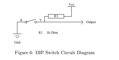
When the switch is open, current flows from five volts through a 1kΩ
resistor. When the swith is closed, a connection is made to ground.
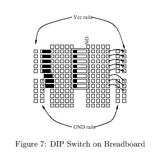
Place a DIP switch on your breadboard and wire it as shown below,
except only wire in three of the eight switches.
Warning! The following diagram is not
consistent with the schematic. The wires and resistors are
reversed. Wires connect ground to the switch, and resistors
connect VCC (5 volts) to the switch.
Connect the outputs of your switches to the inputs of your LED circuit and verify that your switches and LED's work correctly.
Remember everything you did today. You'll have to do it in one-third this time next week.
Take apart your breadboard, neatly put the components away, and go home.