7 April Lab in CSCI 274
Lab goals
- See how multiplexers and tri-state drivers implement buses
Starting off
As usual
- mkdir csci/274/lab10
- chmod go-rx csci/274/lab10
- cd csci/274/lab10
- cp /usr/local/csci/274/lab10/*.lgf .
These commands will place two partial diglog
circuits, multiplx.lgf and tristbus.log, into
your directory.
Remember! Under the CDE (Alpha's and Sun's) you can not start
diglog while netscape is running!
The problem
These circuits are partial solutions to the following RTL
specification:
- P: A <- A+2, B
<- B+3
- Q: A <- B, B
<- A
- R: A <- 0, B <- 0
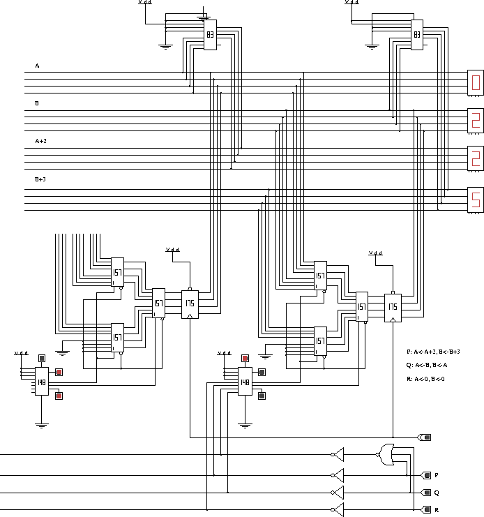
The diglog file multiplx.lgf, show below,
is about 80% of the completed solution. It sets B
correctly, but there are some missing wires need to set
A.

The chips labeled "84" are 4-bit full adders. The right one
computes A+2; the left one, B+3. The chips
labeled "175" are 4-bit registers. There is no quad 4×1
multiplexers chips available in diglog, but you can
build one with three quad 2×1 multiplexers. This construction
is done twice in this partial implementation. Finally, there a
priority encoder, labeled "148", is used to set the selector inputs
to the multiplexer. This is the tricky part of the circuit and the
one you need to which you need to pay the most attention. Turn the
control inputs, P, Q, and R off
and on, and see how the selector inputs change. Study this
carefully!
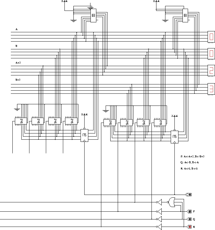
The second partial circuit is an implementation using
three-state drivers on a bus. This implementation is stored in
tristbus.lgf and is shown below

The "245" chips are tri-state buffers. When the input on the
bottom (actually, the left the way the chip is rotated) is 1, the
chip drives the bus. This circuit is not protected against
short-circuits. Try pressing the P and Q
inputs at the same time and see what happens.
Your task
Finish it up!
Return to CSCI 274 labs
Return to CSCI 274 home page
Return to Dean Brock's
home page
 Return to the UNCA Computer Science home
page


