This lab has been created to support UNC Asheville’s sustainability initiative.
Getting ready
You’ll need the follow hardware for this lab. This is similar to the parts required for the Pin I/O on the PIC32 lab.
- One PIC12LF1822 microcontroller (any PIC12 should work)
- One PICKit 3 programmer
- Breadboard — large or medium
- Three 330 Ω or 1 kΩ resistors
- Three LED’s: green, yellow and red
- Two push-down switches
- A small amount of wire
In the last few weeks we have studied the PIC32 in the CSCI 255 labs. We are using the PIC12 this week because it is inexpensive (about 50¢), is easy to wire up, and has simple facilities for controlling power usage.
The PIC12 and PIC32 have very different machine languages; but, since we’ll be programming in C, this is not a consideration. By the way, the PIC12 assembly language was used in the four previous offerings of CSCI 255. You should be glad we switched to the PIC32.
We will not have any pictures of completed breadboards this week. With your present experience, you should be able to populate them from schematics and diagrams. However, we strongly suggest that you work this lab in pairs and have other pairs check your work before applying power to the circuit.
The wiring
You will be wiring your breadboard in several stages. At each checkpoint, you should ask another team to verify that your wiring is correct.
Preparing the breadboard
Make sure all the ground rails and all the power rails are connected. If you are using one of the larger breadboards, make sure that the rails on both halves of the breadboard are connected.
Inserting the chip
First open a copy of the
PIC12LF1822
datasheet
in a new browser window and move to page 5.
Place your chip on the breadboard. I suggest you place it in columns 10 to 14 with the
Vdd and Vss pins in
column 10.
Avoid columns 1 to 6. We will use those later.
Now wire the Vdd (power) and Vss (ground) pins to the appropriate rails.
Be sure to use the appropriate wire colors.
(Some designers suggest
connecting the MCLR pin to power using a
10 kΩ resistors to prevent the PIC12 from resetting due to a power “glitch.” Others say this is unneccesary. We are ommitting the
resistor.)
Wire you breadboard neatly.
Verify that your breadboard is correctly wired with the PIC12 included. If you breadboard has been wired sloppily, the lab instructor may ask you to fix it up.
Wiring the LED’s and switches
Using the 1 kΩ resistors,
connect your three LED’s to the PIC24.
Each resistor should go between ground and an LED lead.
The green LED should be connected to the pin for port RA2;
the yellow, port RA1; and the red, port RA0.
If you are having trouble remembering how to do this, consult the Pin I/O on the PIC32 lab or the Adafruit lesson on digital inputs.
Now place the push-button switches on the breadboard.
Write them so that they will connect ground to the PIC12 when pressed.
Connect your leftmost switch to port RA4 and your rightmost switch to port RA5.
Again, consult the
Pin I/O lab or
Adafruit lesson
if you need a refresher.
Preparing for the PICkit 3
Thus far, the wiring has pretty much the same as what was done in the Pin I/O lab. However, now we must set aside six breadboard columns for a connection to the PICkit 3. We will use columns 1 to 6 which we will wire up before we make the connection to the PICkit.
Open a copy of the PICkit 3 poster in another browser window. Notice the connector pinout tables in the upper-right of the poster.
MCLRVddVssICSPDATICSPCLK- don’t use this one
To keep thing simple, let the pin numbers and breadboard columns numbers match.
Wire the Vdd column (number 2) to the power rail.
Wire the Vss column (number 3) to the ground rail.
The PIC12 has pins that are also labeled
MCLR, ICSPDAT and ICSPCLK.
Wire the corresponding columns and pins for these three.
By the way, the Wikipedia page
on in-circuit serial programming has specific examples of both the PICkit 3 and
PIC12 if you need more information. (I wonder if a Microchip employee worked on that page.)
You really need to be careful at this point. You’ve only added five wires, but they must be connected correctly.
Now it is time to compare your breadboards with at least two other breadboards. This must be done in such a way that the transitive closure of the compared-with relation includes all pairs of breadboards within the room. (The last sentence is for students in CSCI 331.)
Connecting the PICkit 3
Finally, follow the instructions of the PICkit 3 poster to connect the PICkit 3 to your breadboard using the six-connector ribbon cable. Pin 1 of the PICkit 3 is the one with the triangle or arrow.
Make absolutely sure that the PICkit wire with the triangle makes its way to the
MCLR pin of your PIC12.
The lab instructor will want to check this one out.
Going USB
Using a USB cable, connect your PICkit 3 to your computer. The power and active LED’s of the PICkit should light up.
Since you are a Linux geek, you should type the command lsusb to verify that the PICkit 3 was been recognized by the operating system.
The first program — test the breadboard and PICkit
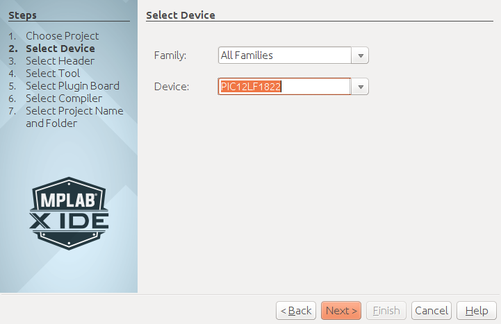
Start up MPLAB X and create a new project. When asked, take the following choices.
- In the Select Device window, choose the PIC12LF1822 Device from the Mid-Range 8-bit MCUs Family.
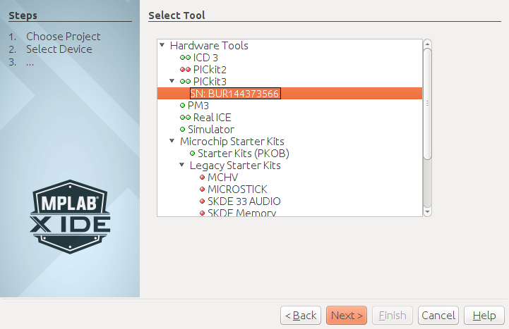
- In the Select Tool window, choose your PICkit 3.
- In the Select Compiler window, choose the XC8 compiler.
You can choose your own project name. You can also click on the following images, if you think they are too small.
 |
 |
 |
Next add a new file, a C Main File from the C category. I called mine stoplight.c.
Delete the initial contents for stoplight.c and replace it
with this main program.
/*
 * File:   CSCI 255 Stoplight lab for PIC12LF1822
 * Author: Your Name here
 */

/*
 * Pins on the PIC12LF1822
 *   Pin  1 --  Vdd
 *   Pin  2 --  RA5
 *   Pin  3 --  RA4
 *   Pin  4 --  RA3  [RA3/#MCLR/Vpp]
 *   Pin  5 --  RA2
 *   Pin  6 --  RA1  [RA1/ICSPCLK]
 *   Pin  7 --  RA0  [RA0/ICSPDAT]
 *   Pin  8 --  Vss
 */

#include <xc.h>
#include "configure.h"
#define _XTAL_FREQ   500000ul
#include <pic.h>

#include <stdlib.h>
#include <stdint.h>

/* All on port A (of course) */
#define GREENLED    2
#define YELLOWLED   1
#define REDLED      0

#define LEFTSWITCH  5
#define RIGHTSWITCH 4

#define GREENLEDMASK     (1 << GREENLED)
#define YELLOWLEDMASK    (1 << YELLOWLED)
#define REDLEDMASK       (1 << REDLED)

#define LEFTSWITCHMASK   (1 << LEFTSWITCH)
#define RIGHTSWITCHMASK  (1 << RIGHTSWITCH)

#define TESTWIRING 1

int main(void) {

    ANSELA = 0 ;                                  // All pins are digital
    TRISA  = LEFTSWITCHMASK | RIGHTSWITCHMASK ;   // Two pins are input
    OPTION_REG = OPTION_REG & ~_OPTION_REG_nWPUEN_MASK ;   // !#$!##
    WPUA   = LEFTSWITCHMASK | RIGHTSWITCHMASK ;   // With weak pullup
    LATA   = 0 ;                                  // Start with 0

#ifdef TESTWIRING
    while (1) {
        uint8_t aMask = YELLOWLEDMASK ;           // PIC12 is 8-bit computer
        if (LEFTSWITCHMASK & PORTA) {
            aMask |= REDLEDMASK ;
        }
        if (RIGHTSWITCHMASK & PORTA) {
            aMask |= GREENLEDMASK ;
        }
        LATA = aMask ;
    }
#endif

    return (EXIT_SUCCESS);
}
Configuring the PIC12
You should notice that one line
#include "configure.h"
is bothering MPLAB X.
First, right click on Header Files, select New → C Header File and add the configure.h file. There is nothing of interest in the present file except for the use of include guards that allow the file to be included many times.
You should be able to build the project now, but don’t bother. We have some more work to do.
We need to generate a configuration for the PIC32.
Use the window choices
Window →
PIC Memory View →
Configuration Bits to bring up the
Configuration Bits window.

You are going to set two Options for the following Fields in this window. Just click on the option name to set it.
- Set FOSC to INTOSC.
- Set WDTE to OFF.
Once you have done this, press the button labeled
Generate Source Code.
This will bring up a window labeled
Config Bits Source which contains lots of C
#pragma statements.
Copy-and-paste this code into the middle (around line 15) of your
configure.h file.
Take a minute to glance through configure.h and then build your project. The PIC12 has about one-fourth of the configuration parameters as the PIC32. Be glad we switched.
Programming the PIC12
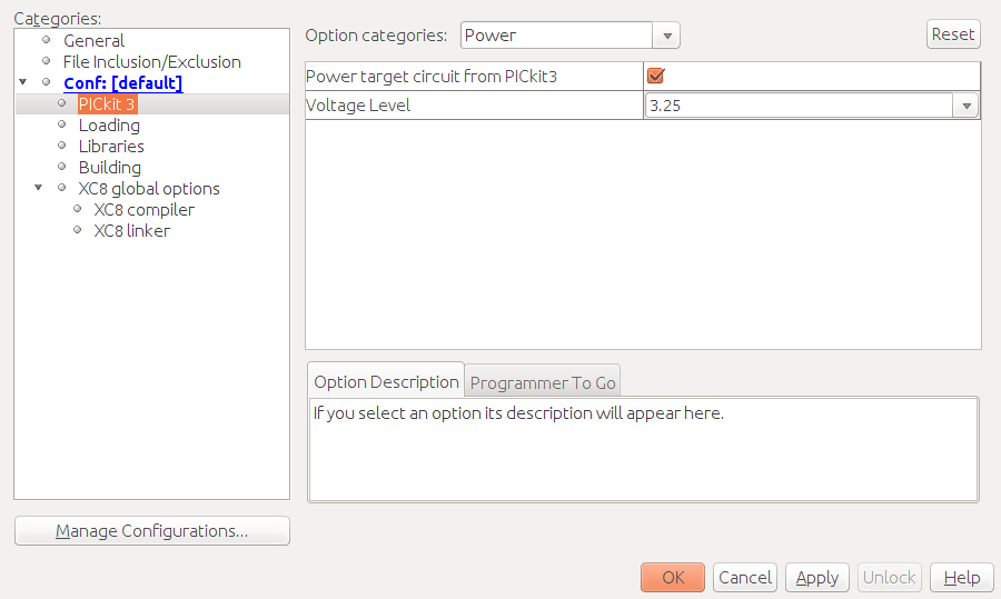
Before continuing, you must set the project properties so that the PICkit 3 is powering the chip.
Right click on the project name and select Properties.
Then click on PICkit 3.
Under Option categories, choose Power
and power the target from the PICkit at 3.25 volts.
(You can try lower voltages, but the LED’s may be hard to see.)
Attach your PICkit to the header and make sure you have the
triangle on the wire heading toward
MCLR.
Go ahead a push the Make and Program Device
icon
![]() to program your PIC32 processor.
You will get an ugly warning:
to program your PIC32 processor.
You will get an ugly warning:
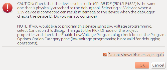
Press the Do not show this message again and
program that chip.
If your PICkit 3 hasn’t been used in a while, it will need to upgrade its firmware. This can take a while.
Testing your wiring
Now you could add the LED’s and switches if you didn't earlier
Initially, all the LED’s should be on. Something interesting should happen whenever you push a button.
If this is not the case, you need to fix your wiring.
Playing with power
Get rid of the existing while loop in main.
You can delete it, comment out, or remove the
#define for TESTWIRING.
Add a new loop that turns on the lights like a fast traffic signal.
- Green for six seconds.
- Yellow for two seconds.
- Red for eight seconds.
This should be similar to the code you wrote in the Pin I/O on the PIC32 lab.
However, instead of using your own spin routine,
use __delay_ms(mSecs), that will pause for mSecs milliseconds.
You can even start with the following loop.
while(1) {
        LATA = GREENLEDMASK ;
        __delay_ms(6000) ;
}
There is one thing you need to know about __delay_ms.
It needs a C preprocessor #define
for _XTAL_FREQ to work properly. If you look near the beginning of your main program, you will
see a line where _XTAL_FREQ is defined as 500000ul.
When you change the clock frequency, you will need to change the value
of _XTAL_FREQ.
By the way, you really need the “ul”
at the end of the literal 500000ul because the int
of the PIC12 only holds 16 bits.
You need a long for 32-bit numbers.
As it turns out, __delay_ms is itself a C macro that calls a
C function _delay. You can find a declaration of
__delay_ms and __delay_us in the
pic.h include file.
extern __nonreentrant void _delay(unsigned long);
// NOTE: To use the macros below, YOU must have previously defined _XTAL_FREQ
#define __delay_us(x) _delay((unsigned long)((x)*(_XTAL_FREQ/4000000.0)))
#define __delay_ms(x) _delay((unsigned long)((x)*(_XTAL_FREQ/4000.0)))
Get the stop light running.
Slowing down the clock
Let’s save a little power.
Take a look at page 69 of the
PIC12LF1822 microcontroller datasheet
which shows the fields of the OSCCON control register.
Look at the IRCF field.
At reset, the IRCF is set to 0111 (0x7 in standard C and
0b0111 in the XC8 dialect). This would be just like having the statement
OSCCONbits.IRCF = 0b0111 ;
at the beginning of your program. (I have relented on C bit fields.)
Test of highest frequency done wrong
First set OSCCONbits.IRCF so that your PIC12 is running at 16 MHz,
the highest clock frequency without using the PLL.
(You can get to 32 MHz using the PLL.)
For now, do not modify the _XTAL_FREQ definition.This will allow you to
experience the speedup.
Test of highest frequency done right
Try again but also give _XTAL_FREQ the right value this time.
Test of lowest frequency done right
Modify both OSCCONbits.IRCF and _XTAL_FREQ to use 31 kHz, the lowest clock rate.
Could you see any difference in the last two? There should be a significant change in power usage, but we don’t have the equipment to measure that one.
The watch dog and sleep
In this section we let the dawg out.
Configuring the dawg
Go back to the Configuration Bits window and set the
WDTE Field to the SWDTEN option.
Generate the configure bits source and copy the changed lines into your personal
configure.h include file.
(By the way, C geeks usually say “dot h” file
rather than “include” file.)
#pragma config WDTE = SWDTEN // Watchdog Timer Enable (WDT controlled by the SWDTEN bit in the WDTCON register)
Go ahead and program your chip. You should see no change.
Enabling the dawg
Go to page 105 of the PIC12LF1822 datasheet
which shows the fields of the WDTCON control register.
Look at the SWDTEN and WDTPS fields.
Enable the watchdog timer with a single statement.
(Hint: In MPLAB X,
type WDTCONbits. and wait for your choices to appear.)
Program your chip. It should stay green because the watch dog timer is resetting the chip every two seconds.
Making the dawg a bit slower to bark
Now let’s use the WDTPS field to set a more reasonable timeout.
Set the watchdog timer period to 8 seconds. This should allow your chip to just start
the red cycle.
(Repeated hint: Type WDTCONbits. and wait for your choices to appear.)
Shushing the dawg for a little while
If your program executes the PIC12 CLRWDT instruction, the watchdog countdown will
be reset to zero. You don’t have to write a whole assembly language program to do this, just
insert an inline assembly statement
asm(" CLRWDT") ;
before each call to _delay_ms.
Insert the calls to asm(" CLRWDT") and program your PIC12.
It should be working now.
By the way, you could have used the C macro call
ClrWdt() rather than inline assembly.
But you really needed to use inline assembly in some course
before you graduate.
Sleeping until awakened by the dawg
Replace the CLRWDT instruction with the SLEEP instruction
asm(" SLEEP") ;
and remove the calls to _delay_ms.
The good news is that we have a very low energy program because the chip does very little during sleep. The bad news is that each light is on for the duration of the watch dog timer, instead of for 6, 2 or 8 seconds.
You need to do some thinking here.
You could try set WDTCONbits.WDTPS to just the right amount of snoozing during
each light cycle.
The only problem is the 6 seconds is not a watchdog timer period.
However, 6 = 4 + 2.
Figure this one out to create a very low-energy solution that spends the right amount of time on each color.
Reality
Of course, the LED’s will still be using energy during the sleep.