In this lab you or going to build a few circuits on a breadboard.
For most of you this will be a new experience.
Work slowly and carefully.
A presentation
Let’s start with a Breadboarding: A Presentation written by Charles A. Schuler for his book Electronics Principles & Applications.
Here’s a bit of what you need to remember.
- The holes of a solderless breadboard are connected by magic.
- The big rows of holes along the edge are bus strips.
- The short columns of five holes on each side of the trough are terminal strips.
- Jump wires are used to connect strips.
- Ground should be connected to the blue bus strip.
- Power should be connected to the red bus strip.
- Use black wires only for connections to ground.
- Use red wires only for connections to power.
- Keep it neat!
Works of Art
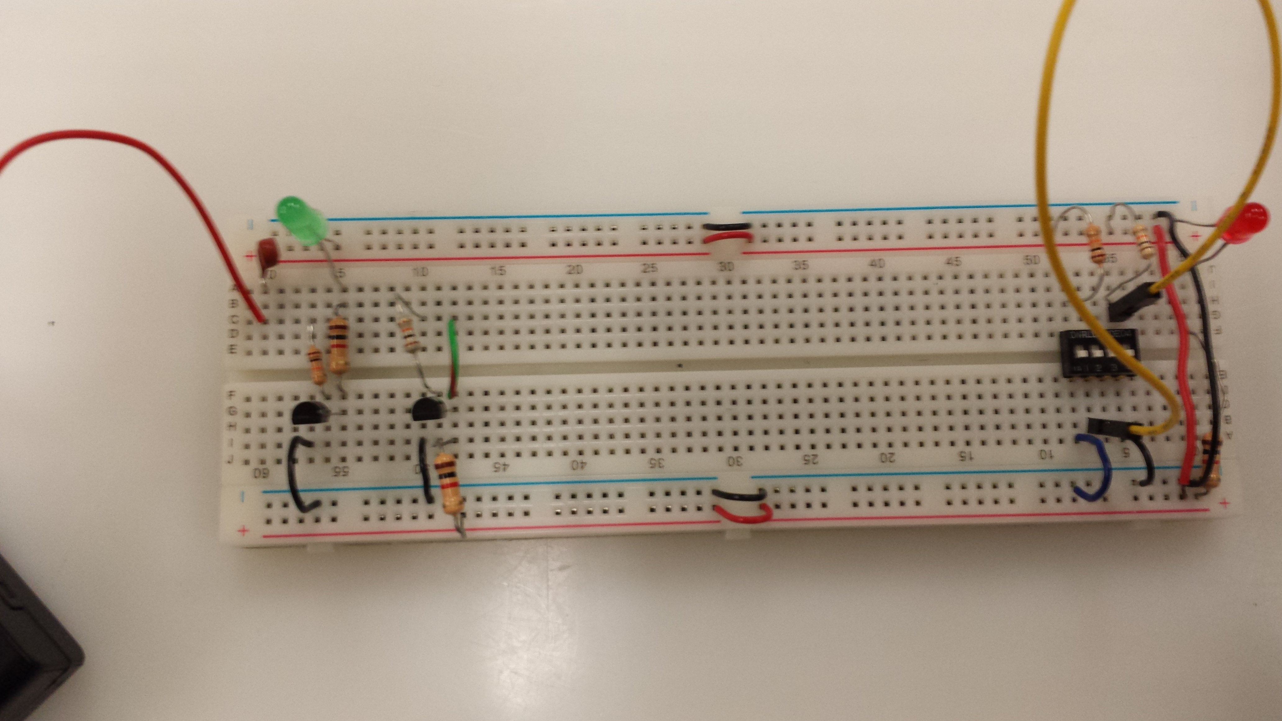
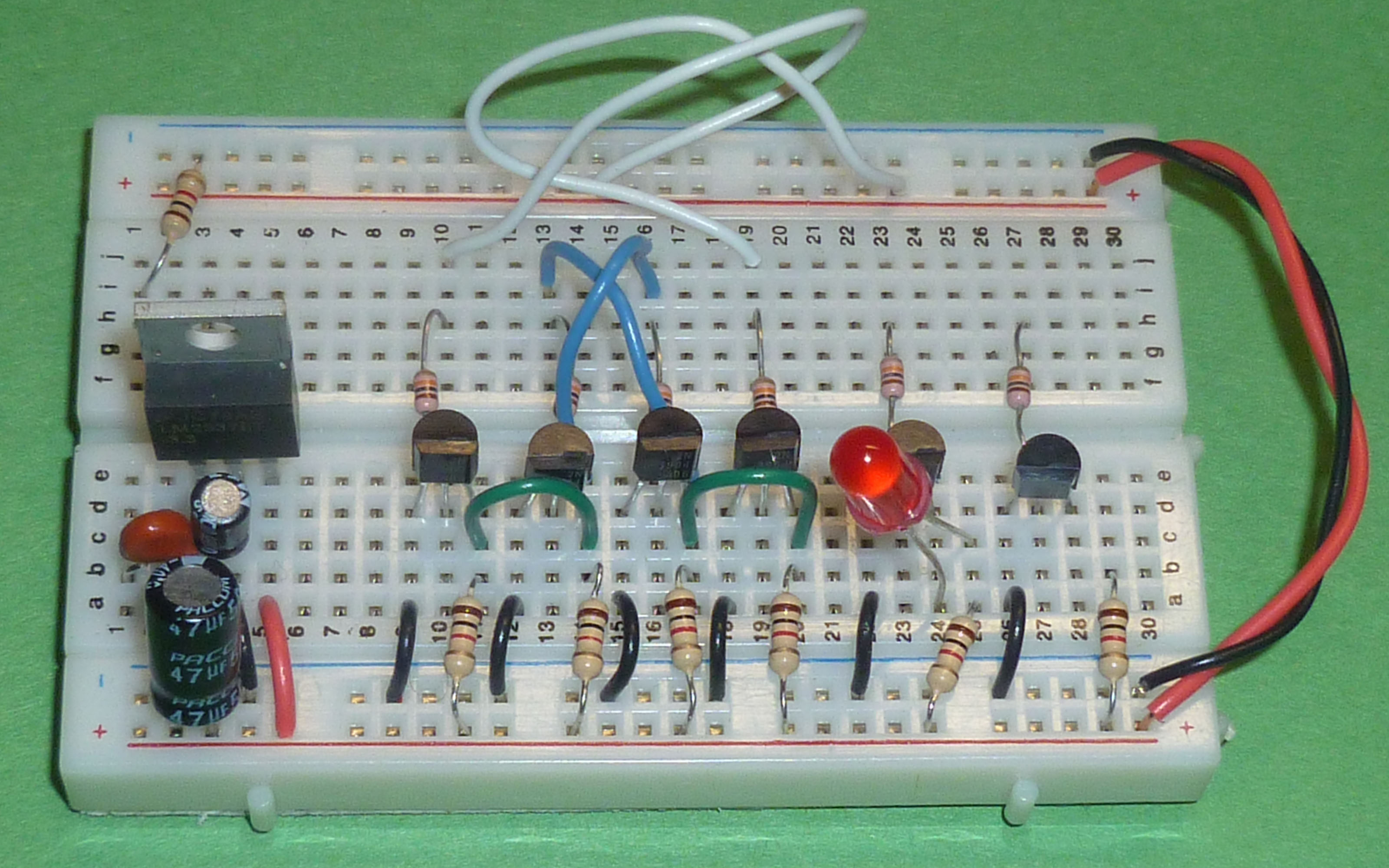
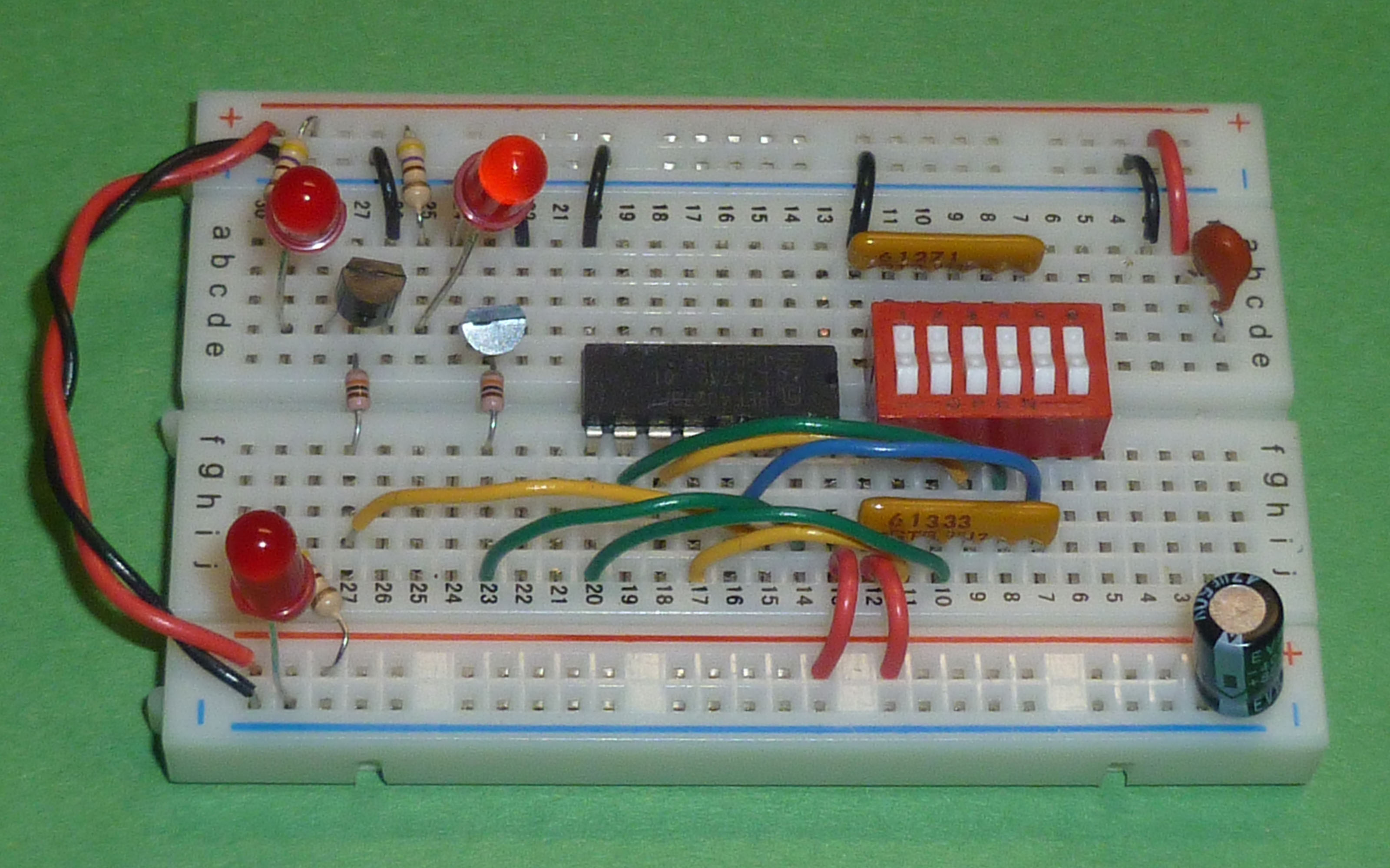
Here’s a couple of breadboards built for a paper we published about
this lab a few years ago.
Stuff you will need
- A breadboard: The small ones are big enough, but the larger ones provide a bit more elbow room
- A battery pack with 4 AA batteries
- A resetable thermal fuse
- One DIP switch
- Three LED’s
- Six 2N3904 transistors
- Six 1 kΩ resistors (Brown-Black-Red)
- Eight 10 kΩ resistors (Brown-Black-Orange)
- Wire
Danger, Danger
It is important that you follow lab directions carefully. If you don’t, you may create short circuits which might make components hot enough to burn your fingers. The smell of burning plastic has permeated the air in previous CSCI 255 labs.
You should also be careful about cutting wires. When making the cut, be sure that the part of the wire that you aren’t holding is pointing toward the table and not toward anyone’s eyes. We’d actually prefer that, when appropriate, you just use the cut pieces of wire left over from previous years. There’s a lot to choose from.
Voltage
Usually you’d use voltage regulators in a computer hardware course; but, since precise voltage levels are not needed for this lab, so we’re going to make do with 4 AA batteries in a pack.
If you really want to know how to build a voltage regulator, look at the Fall 2013 lab on breadboards or make your way through the LM2937-3.3 datasheet.
Using the fuse
We want you to connect power to the breadboard through a resettable thermal fuse. If you short your circuit, the fuse will heat up and break the circuit. At that point, you should fix your short (probably after talking with the instructor) and try again. By then, the fuse should be cool down enough to pass current.
Start by filling your battery holder with 4 AA batteries and turn off the switch on the battery holder. (If you don’t have a switch on your holder, you should probably leave one of the batteries out for a while.) Connect the battery holder to your breadboard on the left end of the board by following these steps.
- Connect the ground lead of the battery holder to the blue bus strip on the lower edge of the breadboard
- Connect the 6 v lead of the battery holder to one end of the resetable thermal fuse
- Connect the other end of the resetable thermal fuse to the upper red bus strip
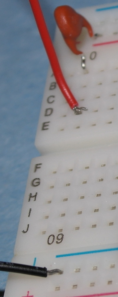
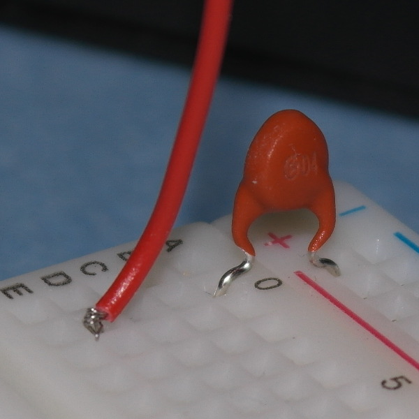
Wire the voltage input end of the circuit.
Be sure that the part with the fuse looks like the following picture.
Connecting the rails
The bus strips on the lower and upper edges are not connected. If you have one of the larger breadboards, it is likely that there are four pairs of unconnected bus strips along the edges of your breadboard. You need to connect these strips. Be sure to use black wire for ground and red wire for the supply voltage.
Power-on LED
Far too often have circuit designers have invested a lot of time “debugging” a circuit that just isn’t receiving any power. We’re going to add a power-on light so that you will know that your circuit is getting the electrons it needs.
Your light will be the
light-emitting
diode (LED).
LED’s can be tricky. They are two things you need to know
before using them.
First, the LED is a diode, a one-way channel for current.
You must orient it correctly in your circuit for it to light up.
The anode must be connected to the higher voltage;
and the cathode, to the lower voltage.
If the leads of the LED have not been cut, the cathode lead will be
the shorter. Often, other students (and instructors) trim
the leads so that they fit closer to the breadboard. In that case, you
must look at the LED from above. The cathode side will either be
flattened or notched.

Second, the LED must be used with a
current limiting resistor.

You can find many
tutorials on LED
circuits
and many LED calculators
on the internet, but just stick with 1 kΩ resistors today.
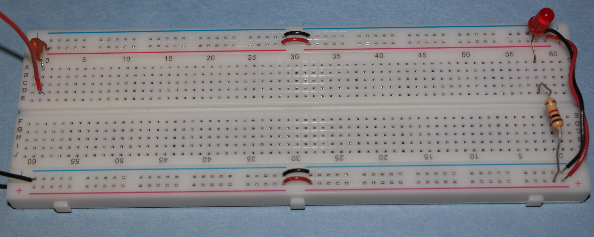
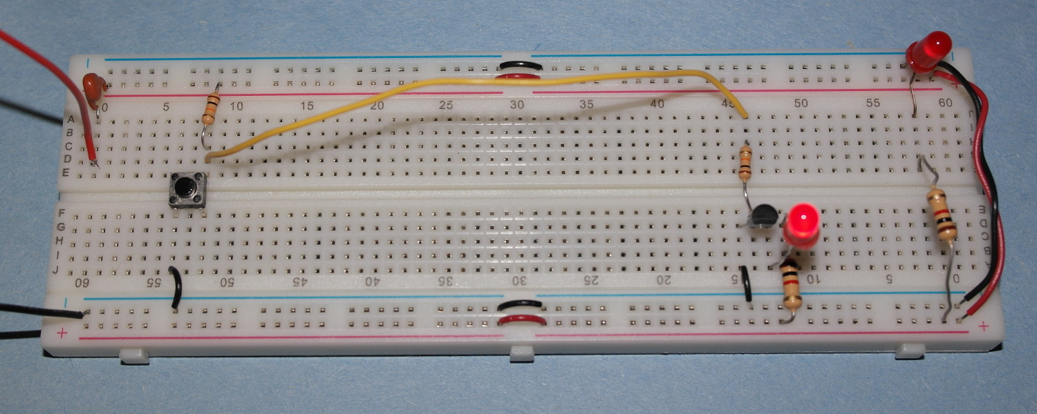
Complete your power supply circuit by adding a “power-on light”
and connecting both
“+” bus strips to the output of the regulator,
and both “-“ rails to ground on the right end of the board.
Be sure that your power light is on.
When you complete this task, your circuit should look something like
the picture below:
Show the instructor your circuit with the power light burning.
Input from and output to humans
You need to be able to communicate with your breadboard. You will give inputs to your breadboard by pressing switches. The breadboard will turn on lights in response to your switch presses.
Input — The switch
This part of the lab may be far more complicated than you expect.
We are going to use small tactile switches for our presses. The switches we use will also be single pole single throw (SPST), which can be either open or closed; and momentary, which return to their usual state as soon are you release the button; and normally open, which are closed only when you are actively pressing the switch. (It is possible that some normally closed switches have infiltrated our supplies. Be on the lookout for this.)
The switches we supposed to stick in the holes of the breadboard:

Unfortunately many of these switches do not fit well in the breadboard
and will pop out occasionally. If this happens, just mash them hard enough to
push them back in.
The wiring within these switches can be confusing.
(Pay attention here. Many students and instructors have wasted
a lot of time because they forget this part.)
An SPST switch really needs only two connections, but these
switches have four.
This is because these tactile switches contains two pairs of wires
and an internal switch that can connect the two pairs.
Here’s a dimensional drawing from SparkFun that illustrates,
in the bottom right corner, the connections.
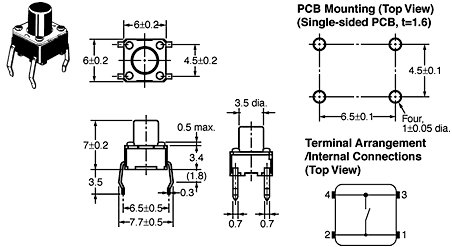
The hard part is remembering that the always-connected pairs run along
the long sides.
To avoid floating inputs to electronic circuits,
pulldown (on left) or
pullup (on right) resistors are used to make sure the switch output, labeled
D,
is always tied to either ground or the supply voltage.

Because many embedded systems provide internal pullups, we’ll use
pullups in this lab with normally open switches. This means that the output
of the switch
is connected to ground when the switch is pushed.
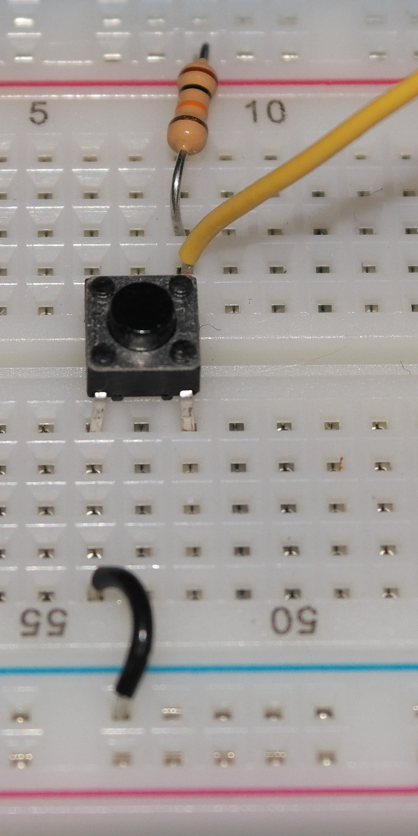
Near the left end of the circuit build two switches in the
pulldown configuration.
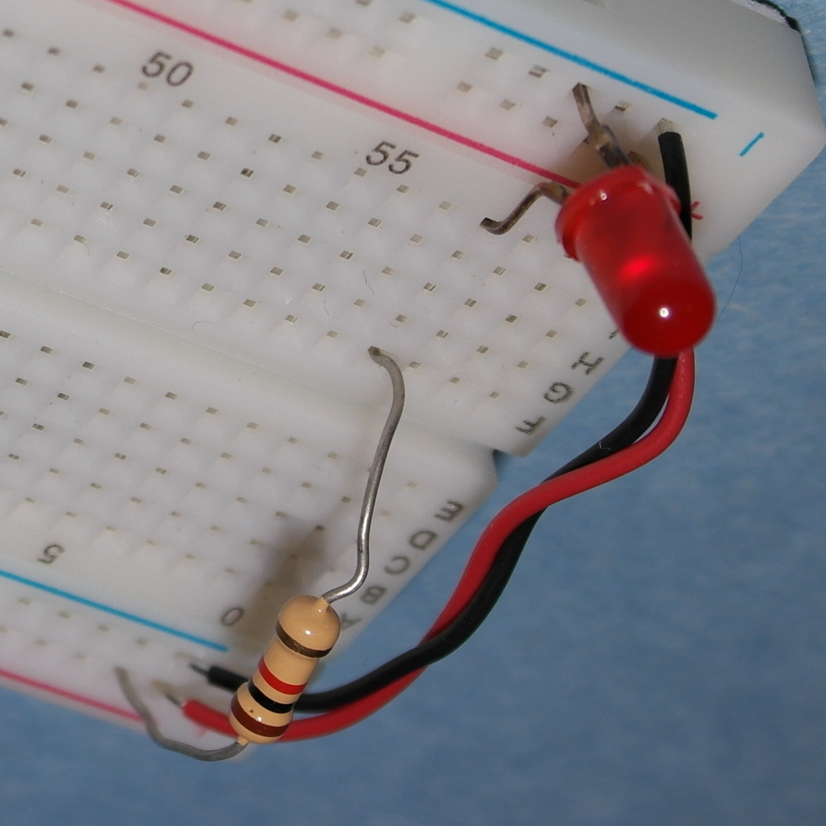
Here is how one of them looks.
The yellow wire marks the output of the switch.
You can try to test your switch by connecting it to
an LED, but the
10 kΩ resistor may restrict the current too much for you
to see that the LED is on.
However, you can use the multimeter to measure voltage.
Output — The LED
We will use a transistor, LED, and a couple of resistors to make an LED driver to allow a small current source to control the LED. LED drivers with transistors look a lot like inverters. In fact, if you remove the LED, you pretty much have an inverter. And, if you add a transistor to the power-on LED circuit you built early, you pretty much have an LED driver.
But first let’s learn a little bit about the 2N3904 transistors we’ll be using this lab. Start with a very quick (no reading allowed) look at the 2N3904 data sheet. The 2N3904, like all bipolar junction transistors, has three external connections: a base, a collector, and an emitter. The design of a transistor allows it to function as an amplifier or a switch. A little bit of current flowing into the base can control a much larger flow of current between the emitter and collector. This is similar to your faucet, where a valve (base) controls the flow from the water supply (collector) to the drain (emitter).
The standard schematic drawing
of a generic NPN transistor is shown below on the left. The 2N3904 is is
made in a TO-92 package. On the right is a picture that illustrate how
its three physical pins are allocated the collector, base, and emitter
functions.


Before using a transistor be sure to look up its datasheet.
The location of the base, emitter, and collector can vary.
To understand a little more about NPN transistors without plowing through pages of textbooks, try out some of Paul Falstad’s excellent Java Applet animations.
Start by opening the NPN animation an another browser tab. Note the following about the NPN:
- The collector should be at a higher voltage than the emitter. This is why the emitter is fixed at 0 V (ground) and the collector voltage cannot be decreased below 0 V.
- The transistor “turns off” as you lower the base voltage.
Back to the lab
Now that you’re familiar with transistors, let’s use one.
- The emitter of your transistor should be connected directly to ground.
- The collector of your transistor should be connected to a 1 kΩ resistor.
- The other end of the 1 kΩ resistor should be connected to the cathode of the LED.
- The anode of the LED should be connected to the power supply.
Finally, the base of the transistor should be connected to a 10 kΩ resistor. The other end of the 10 kΩ resistor is the input to your circuit.
Your new circuit should follow the schematic shown below. (OK, the
LED and current limiting resistor are switched, but that’s
not a problem.)
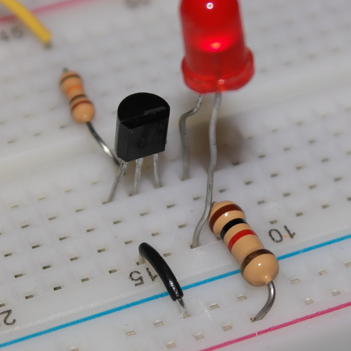
Near the right end of the circuit build two LED drivers
and use the switches on the left end to turn the LED’s off and on.
Your circuit should look a bit like the following, but it should have
two switches inputs and two LED outputs.
Connect the two inputs with the two outputs and demonstrate that you can use the switches to turn the LED’s on and off.
Perhaps you are wondering what is the point of having a transistor-controlled LED driver. Why add the transistor when we are already able to turn on the LED? There are two reasons. First, any digital circuit can turn a transistor on and off. Second, transistors can control devices, such as motors, that require for more current than a digital circuit can produce.
Building some inverters
Your next task is to build four
RTL
(resistor-transistor logic)
inverters in the middle of
your breadboard.
The RTL inverter will be implemented with a couple of resistors and
a single transistor as shown below.
It looks a lot like an LED driver without the LED.
The input to the inverter is connected to
the transistor though a base resistor, Rbas.
There is a collector resistor, Rcol, that connects the high
voltage to the collector of the transistors.
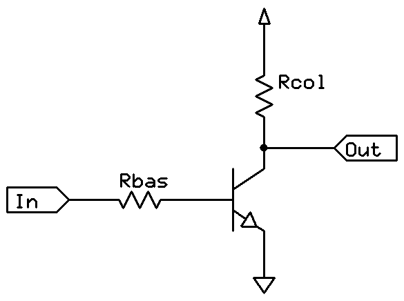
Use a 1 KΩ resistor for Rcol
and a 10 KΩ resistor for Rbas.
There’s nothing magic about these choices. We just happen to have a lot
of them.
(In the drawing above the triangle at the top is a connection to
the power supply and the triangle at the bottom
is a connection to ground.)
We’re not going to give you any more pictures for this lab.
You should be able to follow the schematic.
However, we do suggest you put the transistor and collector
resistor on the bottom half of your breadboard.
Then connect the base resistor and a wire to the transistor’s
collector on the top half of your breadboard as shown in the following
fuzzy picture
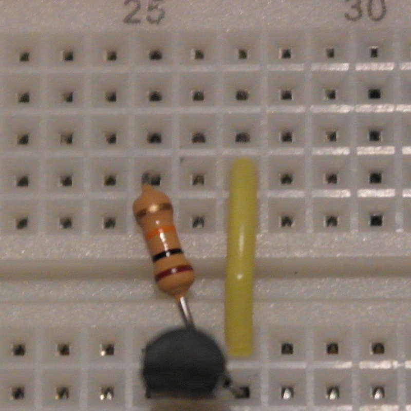
This way it will be easy to find the input and output of
the inverter.
Build four inverters in the middle of your breadboard. Test all four inverters by connecting them to your inputs switches and LED drivers.
The remainder of the lab will be accomplished solely by connected the inputs and outputs of your inverters with wire. No additional transistors or resistors are required.
The NOR Gate
Today, most Boolean functions are implemented with NAND gates. Unfortunately, it is difficult to build a reliable NAND gate with NPN transistors. So, we are going to build a NOR.
Only have NOR gates is not at all a problem when building larger circuits. Any Boolean function can be implemented with two levels of NOR gates using a product of sums, similar to how a sum of products can be used in a two-level NAND implementation.
Here’s an RTL circuit for a two-input NOR.
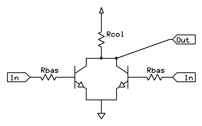
If you are thinking that an NOR looks like
two NOTs sharing a single pull-up transistor Rcol,
you are on the right track.
+
≈
But it’s even better than that because two
1K Ω resistors in parallel make a
500 Ω resistor and a
500 Ω resistor is good enough for our NOR.
(This means you don’t even have to remove the extra
1K Ω resistor to build your NOR gate.)
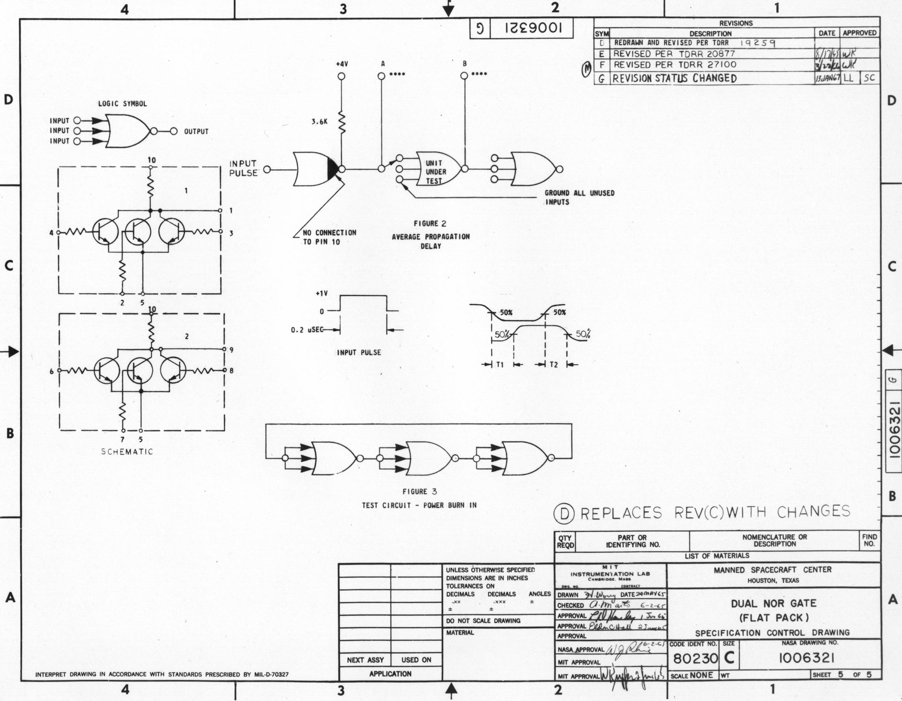
By the way, the Apollo Guidance Computer used about 2,800 RTL chips, each
containing two three-input NOR gates, for all the manned flights
to the moon.
If you click the image below, you will see that our NOR
differs little from NASA’s.
Now use the two inverters on the left side of your board to create your own version of this 1965 classic with a single NOR from two NOT’s by adding one wire!
Demonstrate the functionality of your NOR gate for your instructor.
An OR Gate
NOT your NOR to build an OR using the following Boolean identity.
- x OR y = NOT(x NOR y)
Demonstrate the functionality of your OR gate for your instructor.
An AND Gate
Use your NOR’s with your two NOT’s to take advantage with De Morgan’s law and build an AND gate.
- x AND y = (NOT x) NOR (NOT y)
Demonstrate the functionality of your AND gate for your instructor.
The SR flip-flop
For our grand finale,
build a SR flip-flop by building and connecting
two NOR gates
as shown below. You should already have one NOR on the
left side of your breadboard.
Built the second one on the right side.

Practice setting the outputs of your flip-flop and then show the lab instructor how you can turn the output Q on and off by changing the inputs R and S.