This is an attempt to connect the last few topics: interrupts, UART, and I2C.
Serial communction — UART — RS232
The really old view
Here are a couple of links to some videos about modems.
RS232
The ultimate on-line reference for RS232 is the RS232 Data Interface tutorial. Leave it open in another window.
Perhaps the most dated, and puzzling, RS232 terms are DTE and DCE.
- DTE — Data terminal equipment: the terminal or computer end
- DCE — Data circuit-termining equipment or Data communication equipment: the modem end
Even in the old days, the DCE was relevant only for modem connections. When a terminal was connected directly to a computer, you used a null modem cable.
Here are some nice pictures of an RS232 transmission


The trasmission consists of four parts: start, data, parity, and stop. Parity can be odd, even, or none. By default, Raspberry Pi is 115200/8-N-1: 115200 baud, 8 data bits, no parity, 1 stop bit.
Some questions
How to send out “Hello” in 9600/8-O-1.5? What is the bps of 115200/8-N-1?
Once at UNC Asheville
In the mid-90’s, UNC Asheville provided 2400 and 9600 baud dail-up terminals. These allowed terminal-style connections to a few systems. Serial IP connections, such as SLIP and PPP, were not allowed but many students (and some adjunct faculty) found a way around that prohibition.
These dial-up lines were eventually replaced by campusMCI internet service. Of course, today everyone gets there own internet service.
Flow control
The three-wire RS232 found on the Raspberry Pi and Arduino uses the following pins.
- TxD — Transmitted data
- RxD — Received data
- GND — Ground
With these devices you are usually connecting a DTE to a DTE by crossing over the TxD and TxD. In older times, a null modem cable crossed the TxD and RxD lines.
In a three-wire system, flow control must be in band. An example of this is XON/XOFF. Sending XOFF, 0x19 or CTRL-S, in one direction should turn off transmission in the other. Sending XON, 0x17 or CTRL-Q, turns it back on. This is also called software flow control.
In a five-wire system, flow control is out-of-band using two additional pins, RTS (Request to Send) and CTS (Clear to Send). Raspberry Pi and Arduino hackers sometimes use the XBee to communicate wirelessly. The XBee, which acts like a traditional modem, supports RTS and CTS. The RTS and CTS links are named from the view point of the DTE (terminal or computer). The RTS is sent from the Arduino to XBee to ask if it is OK to send data. The CTS is send from the XBee to the Arduino to indicate it is OK for the Arduino to send data. (See page 14 of the XBee manual which is written from the viewpoint of the modem.) Of course, very few Arduino hackers bother with RTS and CTS.
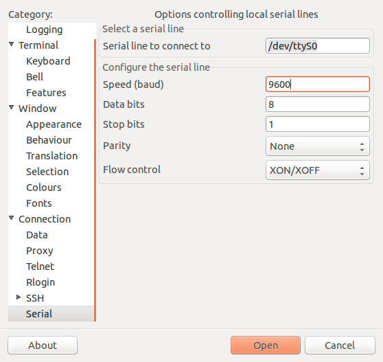
The program PuTTY has a fairly
nice interface for setting up a serial line.
Implementing RS232 on a microcontroller
Because you can compute the length, in µs, of each bit; it is possible to bit bang an RS232 connection with a delay loop. Roman Black has an example of how that can be done on small PIC processor using the built-in timer, rather than a delay loop.
The PIC32 processors, like we are using in class, have specialized hardware and registers for UART communication along with interrupts and buffer. Open up the PIC32 Family Reference Manual, Section 21, UART manual and let’s take a look at some of these facilities.
- p. 21-17, figure 21-3, UART Transmitter Block Diagram
- p. 21-18, section 21.5.3, Setup for UART Transmit
- p. 21-22, figure 21-7, UART Receiver Block Diagram
- p. 21-23, section 21.7.4, Setup for UART Reception
- p. 21-12 to 21-14, section 21-3, UART Baud Raid Generator
The popular microcontroller boards provide RS232 serial connections. The Arduino Uno and the Raspberry Pi provide one RS232 port and the Arduino Mega provides three.
The most popular uses for these ports are for communicating through USB to RS232 converters to a personal computers, through an XBee to a wireless network, through a GSM module to get your SMS messages. or through a GSM module to figure out where you are.