This is the first of a two-week sequence on generating audio with a microcontroller. The first week concentrates on getting a workable program, which will use C pointers and structures. The second week concentrates on delivering power and volume to the product.
It is quite likely that work from the first week will carry into the second.
Platforms
First you need to choose a platform for the lab from three we have used this semester.
What I’d really like is to see you all using a variety of platforms and seeing how that work. For example, two students could work together using both an Arduino and a PIC-based platform.
No matter which platform you are using the initial setup is going to be very similar. You will connect your chip to a single LED through a resistor in the 330 Ω to 1 kΩ range. You will also be given a starter program that blinks the LED for all the platforms.
Read the following sections before making your choices.
PIC32 with Microstick
The initial system should look something like the following:
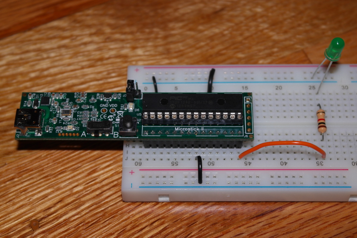
It’s pretty easy to built this system. You need three ground wires
connected to pins 8, 19 and 27 of the Microstick and then a LED and resistor
connected in series to pin 14 (on the corner)
of the Microstick. Pin 14 is
also known as RB5.
The starter program for the PIC32 is longer than that of the other platforms. However, the modifications you make in the lab will be the similar for all three platforms.
/*
 * Pins used in this lab
 * Pin  14 on PIC32MX250F128B  -- RB5
 *     TMS/RPB5/USBID/RB5
*/

/* Program is written for the PIC32MX250F128B-50I/SP
 *   Will run at 40 MHz in case we use the slower chips some day.
 */

#include <xc.h>
#include "configure.h"
#define _SUPPRESS_PLIB_WARNING 1
#include <plib.h>
#include <stdlib.h>
#include <stdint.h>

void spin(uint32_t instructions) ;

/*
 * A slightModification of DelayMS found in
 * http://www.look4tech.com/pic32mx220-demo-project-delay-using-32-bit-core-timer/
 */
#define SYS_FREQ 40000000ul
void delayUS(unsigned int usec)
{
    unsigned int tWait;
    WriteCoreTimer(0);
    tWait=(SYS_FREQ/2000000ul)*usec;
    while(ReadCoreTimer() < tWait);
}

#define OUTPUTPIN   5
#define OUTPUTMASK  (1 << OUTPUTPIN)

int main(void) {

    ANSELA = 0 ;           // Set all pins for digial
    ANSELB = 0 ;
    CNENA = 0 ;            // Disable change notification
    CNENB = 0 ;
    CNPUA = 0 ;            // Disable weak pullup
    CNPUB = 0 ;
    CNPDA = 0 ;            // Disable weak pulldown
    CNPDB = 0 ;
    ODCA = 0 ;             // Disable open drain
    ODCB = 0 ;
    TRISA = 0 ;            // Set all pins for output
    TRISB = 0 ;
    LATA = 0 ;             // Write 0 to output
    LATB = 0 ;

    // Configuration speed -- 8 / 2 * 20 / 2 or 40 Mhz
    SYSTEMConfigPerformance(SYS_FREQ) ;

    while (1) {
        LATB = OUTPUTMASK ;
        delayUS(750000ul) ;
        LATB = 0 ;
        delayUS(250000ul) ;
    }

    return (EXIT_SUCCESS);
}
Of the three, this is clearly the most powerful platform. It is the only one that is a 32-bit processor. It also has a 40 Mhz instruction cycle. (I really think that all our chips are capable of a 50 Mhz instruction cycle, but it is possible that we have some of the older chips in our collection.)
You can download the starter program as an MPLAB X project.
PIC12 with PICkit 3
The initial system should look something like the following:
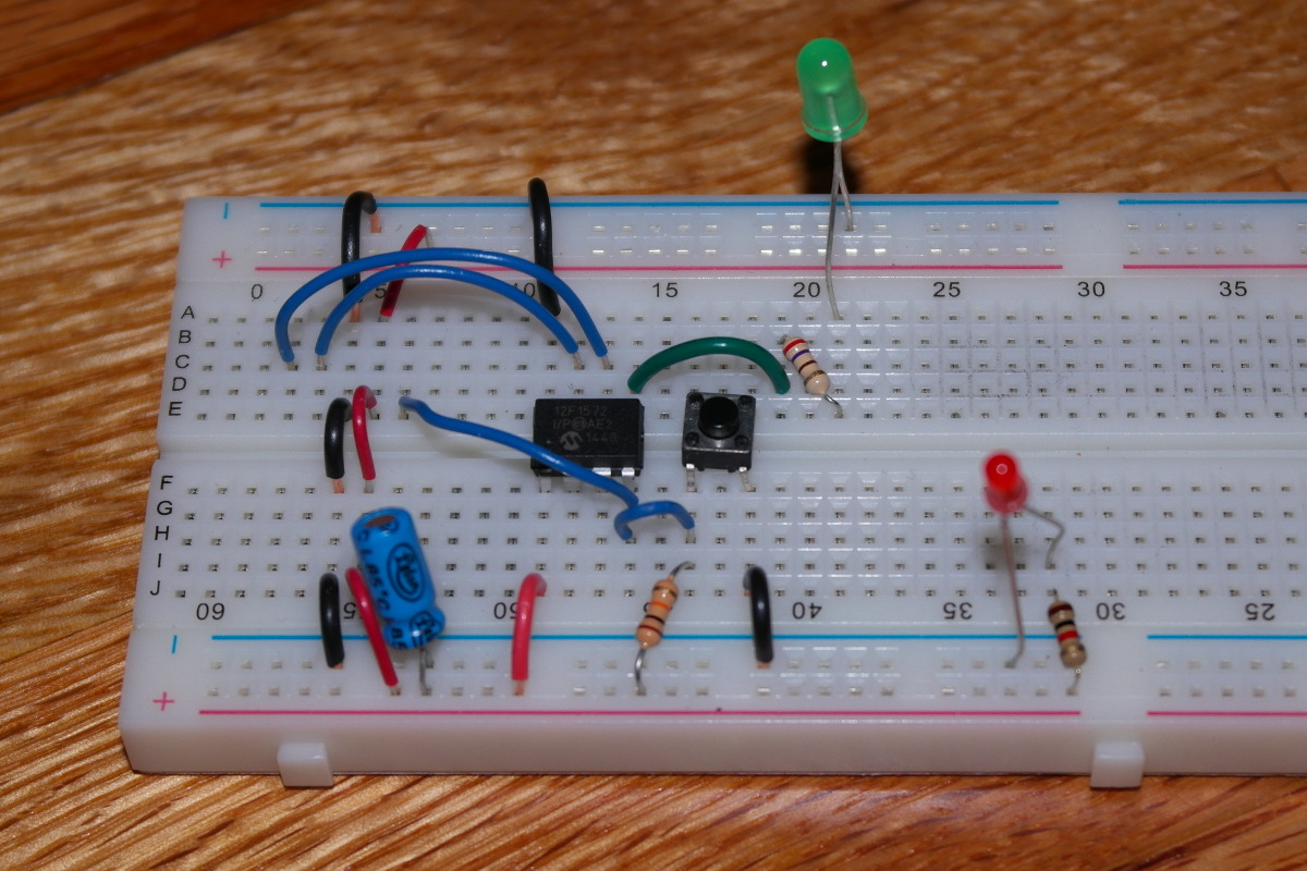
The breadboard you built a couple of weeks ago should
for the Power Management lab
should still be around
for you to use.
All you really need to do is remove the switches and two of the LED’s.
The one remaining LED should be connected to pin 5, also known
as RA2.
The starter program for the PIC12 also has the overhead of initializing the GPIO-related pins. However, it does use a built-in delay function.
/*
 * Pins on the PIC12F1572
 *   Pin  1 --  Vdd
 *   Pin  2 --  RA5
 *   Pin  3 --  RA4
 *   Pin  4 --  RA3  [RA3/#MCLR/Vpp]
 *   Pin  5 --  RA2
 *   Pin  6 --  RA1  [RA1/ICSPCLK]
 *   Pin  7 --  RA0  [RA0/ICSPDAT]
 *   Pin  8 --  Vss
 */

#include <xc.h>
#include "configure.h"
#define _XTAL_FREQ 32000000ul
#include <pic.h>

#include <stdlib.h>
#include <stdint.h>

#define OUTPUTPIN   2
#define OUTPUTMASK  (1 << OUTPUTPIN)

int main(void) {

    OSCCONbits.SPLLEN = 1 ;
    OSCCONbits.IRCF = 0b1110 ;

    ANSELA = 0 ;                                  // All pins are digital
    TRISA  = 0 ;
    LATA   = 0 ;                                  // Start with 0

    while (1) {
        LATA = OUTPUTMASK ;
        __delay_us(750000ul) ;
        LATA = 0 ;
        __delay_us(250000ul) ;
    }

    return (EXIT_SUCCESS);
}
Again the starter program can be downloaded as an MPLAB X project.
The PIC12 has been configured with a 32 Mhz clock. However, because it is an 8-bit processor, it will require four instructions to add 32-bits while the PIC32 only requires one. I doubt you will notice the difference.
Arduino with breadboard
You will need a breadboard when using the Arduino.
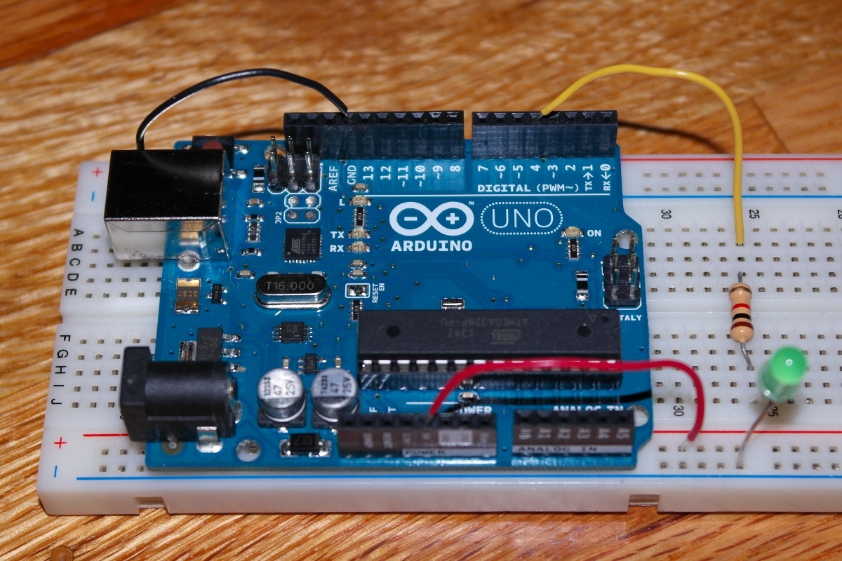
You need to connect an LED and resistor, in series, to digital pin 4
of the Arduino. The 5V and GND of the Arduino
must also be connected to the power and ground rails of the breadboard.
Be sure the all power rails and all ground rails
of the breadboard are connected.
As expected, the Arduino program is the smallest, because the port initialization is built into the Arduino library routines.
int outputPin = 4;

void setup() {
  pinMode(outputPin, OUTPUT);
}

void loop() {
  digitalWrite(outputPin, HIGH);
  // delayMicroseconds does not work with values greater than a "few thousand microseconds"
  // delayMicroseconds(750000ul);
  delay(750) ;
  digitalWrite(outputPin, LOW);
  // delayMicroseconds(250000ul);
  delay(250) ;
}
When using the Arduino, you will need to switch between using
the delay and delayMicroseconds functions
if the delay is more than about 18000 µs.
If you want to use the Arduino, you can just start the arduino IDE and cut-and-paste the code.
Why stick with one?
By the way, you can try out, with a partner, both an Arduino and PIC solution. We have plenty of boards.
One more thing about power
The PIC32 Microstick does not provide a source of
Vdd.
However, don’t assume this means more work.
We are going to have you build voltage regulator circuits for your board
no matter which you choose.
That is something you must know how to do because you will need
to power your circuit from batteries someday.
The Aruduino will be bit harder here because it requires 5 volts rather than 3.3 volts. You will need six AA batteries rather than four to power the regulator.
PWM of LED
In preparation for making sound, we want you to use pulse width modulation (PWM) to dim your LED. You did a little of this in the Pin I/O on the PIC32 lab.
Presently you have two statements that cause your LED to be on for 750000 µs. That should look something like this:
        LATA = OUTPUTMASK ;
        __delay_us(750000ul) ;
Modify your program so that it replaces these two statements with a loop. The loop will generate PWM by bit banging. It will have a period of 1 ms and a duty cycle of 50%. This means the LED will be on for 500 µs and off for 500 µs. You did something like this in the Pin I/O on the PIC lab. You can’t see the LED flashing on and off; but, because it is only on 50% of the time, it may appear to be dimmer.
This is pulse width modulation. This is pretty much the way the light dimmers in your living room work. They turn the light on and off about 120 times per second, and your eyes just don’t notice the difference. (However, standard fluorescent light (CFL) bulbs do notice the difference, so you need to purchase special dimmable CFLs for those dimmer circuits in your home.)
Modify your program to light the LED with a duty cycle of 50% as explained above.
Now for sound
Your program should now be generating a 1000 Hz signal. That should be close to a soprano’s high C. See if we can hear it.
Get a speaker and plug it into your breadboard. Just replace the LED with the speaker. You should be able to hear a faint tone.
The tone will be a bit unmusical because it is being generated by a square wave. A sine wave would be more pleasent, but that requires more mathematics, a mufaster processor, and some well-designed filters. For the most part we are going to concentrate on generating songs this week and loud songs next week.
Modify your program so that it plays two alternating tones, one at 500 Hz and another at 250 Hz. Each tone should last 750 ms and should be followed by a 250 ms pause. This is largely a cut-and-paste-and-modify.
A useful function
Right now you have written
a loop to generate alternating tones.
Let’s write a C function playTone to do this.
playTone take two arguments, the frequency
of a note in Hertz and the
duration of the note in milliseconds.
Start by replacing your loop for playing the alternating tones with this much simpler loop.
   while (1) {
       playTone(500, 750) ;
       playTone(0, 250) ;
       playTone(250, 750) ;
       playTone(0, 250) ;
   }
Now add the outline for a function playTone at
the end of your program, after main (or
loop for the Arduino).
void playTone(int frequency, long duration) {
    // frequency:  frequency of the tone in cycles per second (Hz)
    //             if frequency is 0, play no tone, that is, take a rest
    // duration:   length of the tone in milliseconds (msec)
}
give
In C and C++ it is considered good style to provide prototypes
for functions. This allows the compiler to do some type checking.
C/C++ prototypes are a bit like method signatures in Java.
Add a one-line prototype for playTone
before your main function, so that the compiler will know
the types of the arguments for playTone when
it is compiling main
void playTone(int frequency, long duration) ;
We are using long as the type of the second parameter
because the int of the Arduino and PIC12 is only
16-bits long.
It would really be better to use uint16_t for
frequency and uint32_t for duration,
but that is not part of the usual Arduino style.
Usually functions are written in their own .c files and distributed with corresponding .h files containing prototypes and other useful constant and data structure definitions, but here we are placing the prototype and implementation in the same file.
Complete the playTone procedure.
We must work in units of microseconds inside the
procedure. Start by computing both the period and duration
in microseconds. This means you must multiply the duration by 1000
at the beginning of your program.
Test playTone with your
modified for loop.
What about a song?
Let’s take advantage of the work of someone else, even if it was done for an Arduino. In another window open up the Arduino tutorial Play a Melody using the Tone() function written by Tom Igoe. Read the tutorial.
Now download Igoe’s
pitches.h and place it into
your MPLAB X project
or Arduino sketch.
You also ought to open another window with the
Arduino sketch and take a look at Igoe’s
setup function. This looks like something you
could use in your main routine.
Make your main function look a lot like Tom Igoe’s
setup function.
This isn’t that hard. Start with a cut-and-paste and them make
the needed adjustments.
By the way, this is the sort of thing embedded systems programmers do
frequently.
Now play your song over and over and over, but add a delay
of about one second between performances.
If you wish, you may encode a melody of your own choosing.
Pointers and structure in C
So have just you had written a routine
playTone to play a tone at a
frequency, given in Hz, for a duration, given in milliseconds.
Here’s the C/C++ prototype for that function.
void playTone(int frequency, long duration) ;
Our representation of a note has an abstraction issue. The note is a real-world entity: We shouldn’t be splitting the note into two arrays, one for frequency and the other for duration. We should have an array of C structures that represent notes.
So add the following structure definition at the front of your program,
close to the prototype you have for playTone.
struct noteInfo {
   int  frequency ;    /* frequency in Hz */
   long duration ;     /* duration in mSec */
} ;
typedef struct noteInfo Note ;
Note the slight resemblance to a Java class definition.
Right now your program should have two array definitions borrowed from Tom Igoe’s Arduino tutorial. This is how Tom Igoe wrote them:
// notes in the melody:
int melody[] = {
  NOTE_C4, NOTE_G3,NOTE_G3, NOTE_A3, NOTE_G3,0, NOTE_B3, NOTE_C4};

// note durations: 4 = quarter note, 8 = eighth note, etc.:
int noteDurations[] = {
  4, 8, 8, 4,4,4,4,4 };
Replace these two array of int definitions with a
single array of Note definitions.
It starts with the following:
Note song[] = {
  { NOTE_C4, 1000/4 },
Add the definition for Note and the initialization
for song into your program.
Of course you could continue to call playTone
with something like playTone(song[i].frequency,song[i].duration)
but you really ought to pass a Note;
or, since this is C, a pointer to a Note.
Start by updating the prototype for playTone.
void playTone(const Note *tone) ;
Modify the prototype for playTone.
Also modify the calls to playTone in main
to match the prototype.
Expect the IDE to complain while you do this.
Now you need to turn your attention to the implementation of
playTone.
Now modify playTone to accept a pointer to a Note
as its single arugment.
It won’t be much more than changing the function header and
updating references like frequency to
note->frequency.
At this point you should be able to compile and test your modified program.
Fixing it up
If you have, move your functions to a separate compilation unit, the Java word for a file.