In this lab we are going to use MPLAB® X IDE and its associate XC32 compiler to write and debug a PIC32 assembler program. The MPLAB X software is NetBeans based and will run under Linux, Mac and Windows.
You can download your own copy of MPLAB X from Microchip’s MPLAB X download page. You will want a copy of the following:
- MPLAB X IDE – v2.20 is installed in the lab
- MPLAB XC 32 Compiler – v1.33 is installed in the lab
You can get a short list of instructions from the MIPS “Green Card”. Section 2 of the PIC32 Family Reference Manual, CPU for Devices with M4K core If you want 274 pages about MPLAB X, check out the MPLAB® X IDE User’s Guide. The definitive guide to the XC32 assembler is the 234 page MPLAB® XC32 Assembler, Linker and Utilities User’s Guide. Information relevant to the assembler is also contained in the MPLAB® XC32 C/C++ User’s Guide.
Getting Started
From the command line you can type mplab_ide or you can type “mplab” in the search box at the top of the launcher. Be sure to select MPLAB IDE and not MPLAB IPE. (IPE is Integrated Programming Environment. In embedded system design, “programming” is the process of downloading code to the chip.)
If you’ve used NetBeans, you’ll feel at home with. MPLAB X.
First Project in MPLAB X
Creating the project
Use the menu choices File ⇒ New Project... to begin the process of creating a project. Then work your way through a few windows.
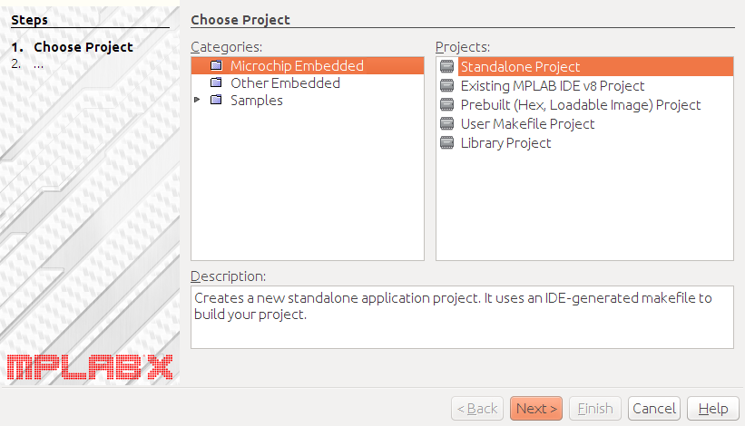
- In the Choose Panel window, from the Microchip Embedded category choose a Standalone Project.
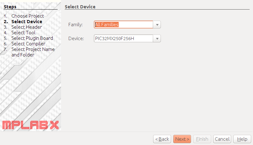
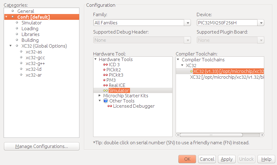
- In the Select Device window, select any device from the 32-bit MCUs (PIC32) family. I chose PIC32MX250F256H. Next time you’ll be able to speed up this process by choosing the Recently Used family.
- In the Select Tool window, go for the Simulator.
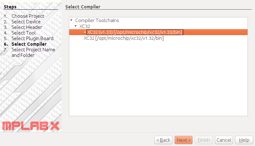
- In the Select Compiler window, select a XC 32. There should be only one choice.
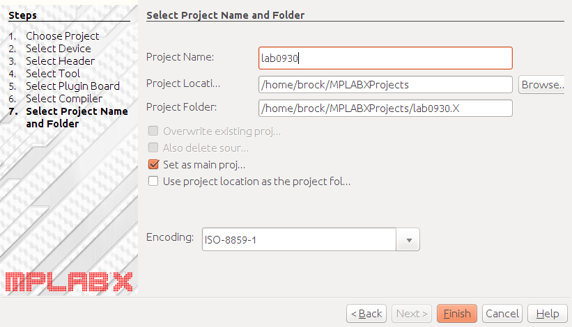
- In the Select Project Name and Folder window, think of a clever project name and and click Set as main project.
You can click on the following images, if you think they are too small.
 |
 |
 |
 |
 |
You may have noticed that many of selected choices were preceded by a little green dot. Avoid the ones with the red and yellow dots.
Let’s mention a couple of things before going on.
There were a lot of devices to choose from. If you are using the simulator, as we are today, you don’t have to be that precise in your selection, but usually you must choose the device the that matches the one you plan is use in your project.
The XC 32 is Microchip’s latest compiler for its 32-bit processors. We are using the free (unlicensed) version. The free compiler is based on the gcc toolchain and it does not optimize your C code. It will cost you about $1000 to get the optimizing “PRO” compiler.
Also, notice that your projects are going to be stored in directories with names that end with a capital X, such as CSCI255rocks .
Click on the name of your project and then select Properties. Make sure you have chosen well.
Checking it out the IDE
At this point you have a NetBeans environment that will be familiar to alumni of CSCI 181 and 202. Move your mouse over the menu choices at the top of the window, from File to Help. Press on the choices to look at their submenus. Pay particular attention to items under Debug. Most of the choices are presently grayed out, because they can’t be used until you are working on a project.
Notice that the lower left corner is occupied by a Dashboard display. The Microchip PIC devices have very little memory so we need an easy-to-use means of figuring out how much memory our programs are using.
Adding an assembler program
Now we’ll use the menu to create an assembler program. Start with the menu choices File ⇒ New File...
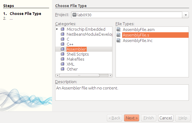
- In the Choose File Type window, take category Assembler category and type AssemblyFile.s . You must to make the .s choice.
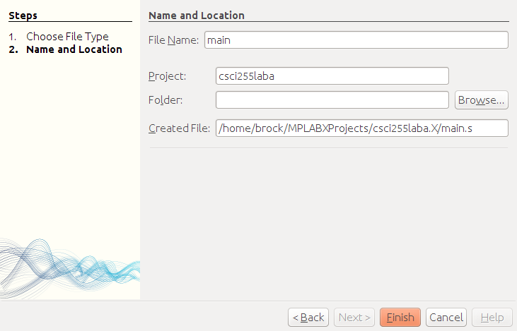
- In the Name and Location window, choose a name for your file. I suggest something like whatever . MPLAB X will add the .s to your filename.
 |
 |
At this point, you should have an empty program in the upper-right window. Make sure that your program really is under Source Files.
Copy the following program into your empty window.
#include <xc.h>
.global main
.data
a: .int 2
b: .int 8
c: .int 17
x: .int 10
z: .int -1
.text
.set noreorder
.ent main
main:
## z = a*x*x + b*x + c
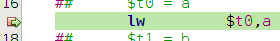
## $t0 = a
lw $t0,a
## $t1 = b
## $t2 = c
## $t3 = x
## $t4 = a*x
mul $t4,$t0,$t3
## $t4 = $t4*x
## $t5 = b*x
## $t4 = $t4+$t5
add $t4,$t4,$t5
## $t4 = $t4+c
## z = $t4
spin: j spin
nop
.end main
Go ahead and press the hammer to built it, so we can make sure your installation is working.
This program is the start of an assembly language implementation of this statement which can be in Java, C++ or C.
z = a*x*x + b*x + c
What’s it all about
But clearly this isn’t Java, C++ or C.
Let’s look at this program for a minute. Like most assembly language programs, this one contains several pseudo-ops or directives. These are lines of code that don’t create instructions. They may define space for variables or control the assembly process or even control the spacing for a printout of your code.
The program starts with the directive:
#include <xc.h>
which would a legal statement in either C++ or C.
This causes the assembler to include a file defining useful constants
for programming PIC microcontrollers.
Open up the file
/opt/microchip/xc32/v1.33/pic32mx/include/xc.h in MPLAB X.
Be sure to use
Open File... and not
Open Project... !
That one isn’t that interesting. It’s just a list of include files
for several different PIC processors. Try again, but this time open
/opt/microchip/xc32/v1.33/pic32mx/include/proc/p32mx250f256h.h in MPLAB X.
Using
Edit ⇒
Find... or simply
Ctrl+F find the definition of
PORTB, the special function register you used in the
Arduino lab.
The volatile keyword is common to Java and C and denotes a variable
that can be changed by external forces.
We are serious. You need to know how to navigate the file system from
the IDE. Show us the line defining PORTB.
Now close those two big system files and get back to your program.
The second line in your program is also a directive:
.global main
This causes the assembler to announce
main as an external variable of your program.
This means that the outside “world” will know about
main.
This is a bit like declaring a method public in Java.
Since ancient times, running programs have been considered to consist of four segments:
(1) the text segment, which contains compiled code;
(2) the stack segment, which contains local variables used by functions or methods;
(3) the heap segment, which contains dynamically allocated memory, such as Java objects; and
(4) the data segment, which contains global variables. The data area also contains the oddly name bss (block started by symbol) segment which contains space for uninitialized data.
In this program, you see that both a text and data segment are defined.
The data segment reserves room for the five variables
a, b, c and z.
The text segment contains the PIC instructions.
Executing a program
The Microchip simulator does know how to simulate the PIC instructions of your program, but right now your program does little more than loop forever. To see anything interesting you must step through the program.
Getting ready to run
To do this you need to know how to set breakpoints in
your program.
Move your mouse onto the narrow column of program line numbers just
to the left of the first real instruction,
the lw, of your program and click.
There should put a little red square in the line number column
and highlight the entire line in red to show that you have
set a breakpoint.
Now use the menu choices
Debug
⇒
Debug Project. This should start the
simulation but stop at the breakpoint.
Put the break in your program and run your program to the breakpoint. If you have done this before using NetBeans, help out any lab neighbors who haven’t.
You will notice a bunch of new tabs in the lower right panel.
One of them is called
Variables.
Go over to the Variables tab
and add a watch for all your variables.

However, all the action if with the registers.
Use the window menu choices
Window ⇒
PIC Memory Views
⇒ CPU Registers
to bring up a new tab called CPU Memory.
Use the arrow keys to find registers $t0
to $t5 in this display.
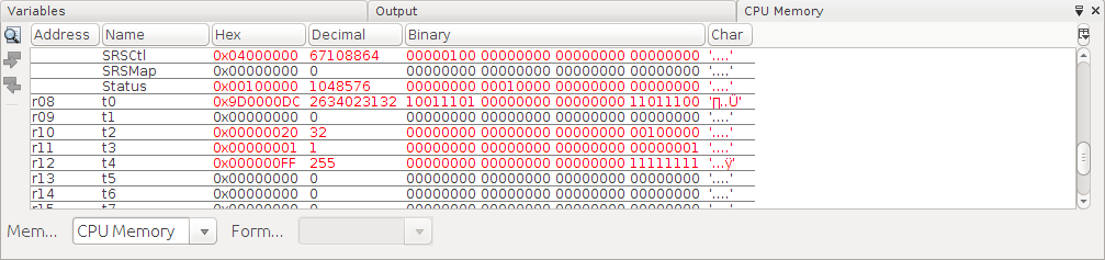
By checking within the Hex or columns of the CPU Registers, you can change the values of registers.
Set the values of
registers $t0
to $t5.
Now use
Window ⇒
PIC Memory Views
⇒ Execution Memory
to see your assembly code translated into machine code
in the Opcode column.
The lw assembly language statement has
been translated into a two-instruction machine language sequence.
We will explain that in class.
Completing the program
Right now only three of the ten simple assignment statements have been completed. Complete the remaining seven and build your program.
You will need to use the sw instruction for the last
assignment.
Debugging with the simulator
It’s time to run some code. Use the F8 key to step through your program while looking at the CPU Registers to see changes in the registers. It will not take long until something goes wrong.
Step through the program one instruction at a time. After each instruction, verify that the expected result has been stored in the destination register.
Stop at the first instruction where something does wrong.
More problems with delay
There are some MIPS instructions that do not immediately produce a result.
One of these is the jump (j spin) instruction
near the end of your program. It does not jump immediately, but
always execute one more instruction in a
delay slot
before transferring to its target.
In our program, the delay slot is filled with a
nop instruction.
The MPLAB X simulator also believes that the mul
instruction requires one delay slot before it can store the result of
the multiplication in the destination register. Add some nop
instructions to your program to provide for these delay slots.
Again step through the program one instruction at a time.
Run your program until it stores 297, 0x129 in
hexadecimal, in z.
Improving your program
You can make your program a little by using those delay slots for useful
work.
Figure out how to fill a delay slot by
moving a lw into a nop slot.
This is not a hard way
to reduce number of instructions by two.
You could also perform $t5 = b*x a little earlier
and get rid of the last nop.
However, not all instructions require the same amount of time.
A multiplication take many more clock cycles than an addition.
If you really want to speed up your program, use the following assignment
to reduce the number of multiplications from three to two:
z = (a*x+b)*x + c
If time permits, make at least one improvement to your program.
In case of trouble....
If your windows get completely messed up, try some of the following:
- Window ⇒ Reset Windows
- Window ⇒ Output ⇒ Output
- Window ⇒ Debugging ⇒ Variables