This is the second of a two-week sequence on generating audio with a microcontroller. The first week concentrated on getting a workable program. In this second lab we are going to have three goals. I hope we satisfy at least two of them.
- Using C structures with pointers
- Controlling speakers and motors with a microcontroller
- Power regulation
Getting started
You can continue using three same three platforms we used last week. This week we are providing starter programs. These are solutions to last weeks lab that don’t include the C structure enhancements.
Pointers and structure in C
So have just you had written a routine
playTone to play a tone at a
frequency, given in Hz, for a duration, given in milliseconds.
Here’s the C/C++ prototype for that function.
void playTone(int frequency, long duration) ;
Our representation of a note has an abstraction issue. The note is a real-world entity: We shouldn’t be splitting the melody into two arrays, one for frequency and the other for duration. We should have an array of C structures that represent notes.
So add the following structure definition at the front of your program,
close to the prototype you have for playTone.
struct noteInfo {
   int  frequency ;    /* frequency in Hz */
   long duration ;     /* duration in mSec */
} ;
typedef struct noteInfo Note ;
Note the slight resemblance to a Java class definition.
Right now your program should have two array definitions borrowed from Tom Igoe’s Arduino tutorial. This is how Tom Igoe wrote them:
// notes in the melody:
int melody[] = {
  NOTE_C4, NOTE_G3,NOTE_G3, NOTE_A3, NOTE_G3,0, NOTE_B3, NOTE_C4};

// note durations: 4 = quarter note, 8 = eighth note, etc.:
int noteDurations[] = {
  4, 8, 8, 4,4,4,4,4 };
Replace these two array of int definitions with a
single array of Note definitions.
It starts with the following definition:
Note song[] = {
  { NOTE_C4, 1000/4 },
Add the definition for Note and the initialization
for song into your program.
Of course you could continue to call playTone
with something like playTone(song[i].frequency,song[i].duration)
but you really ought to pass a Note;
or, since this is C, a pointer to a Note.
Start by updating the prototype for playTone.
void playTone(const Note *tone) ;
Modify the prototype for playTone.
Also modify the calls to playTone in main
to match the prototype.
Expect the IDE to complain while you do this.
Now you need to turn your attention to the implementation of
playTone.
Now modify playTone to accept a pointer to a Note
as its single argument.
It won’t be much more than changing the function header and
updating references like frequency to
note->frequency.
At this point you should be able to compile and test your modified program.
Power regulation
Suppose you wanted to make a battery-power computer-controlled circuit. This isn’t trivial because the voltage produced by batteries varies much more than a computer chip can tolerate.
To produce the right voltage you need a voltage regulator.
Because the Arduino and PIC MicroStick contain voltage regulators in addition to their
microcontrollers, there is little purpose in building a voltage regulator for them.
On the Arudino Uno,
if you connect a battery pack with a voltage of between 7 and 12 volts between the
GND and Vin connectors the internal voltage regulator will generate
5 regulated volts for the chip. By the way, you will need more at least 6 AA batteries
to generate 6 volts and,
if you connect the battery in the
wrong direction, you will destroy your Arduino.
So let’s build a regulated 3.3 v supply that could be used for a PIC12 chip on a breadboard.
Needed supplies
- Breadboard with LED and resistor, if you don’t already have breadboard with a PIC12
- Battery pack with 4 AA batteries
- 1 10 µF capacitor
- 1 1 µF capacitor
- optionally, a fuse
- 1 3.3 v regulator
You will be using polarized electrolytic
capacitors to built the power supply.
It is very important that you always connect the lead closest to the minus sign (-)
to ground.
Otherwise the capacitor can explode!
(There are many YouTube videos of
exploding capacitors.)
It isn’t hard to build a 3.3 voltage regulator with a
LM7833 and a couple
of capacitors.
Here’s a schematic for building one with an LED power-on light.
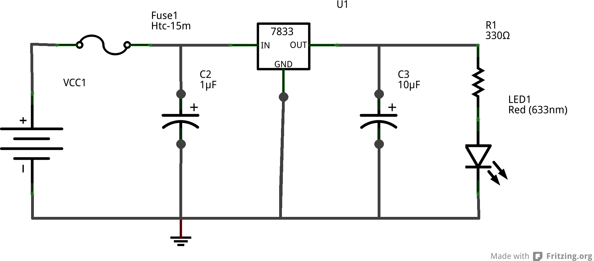
Use the smaller capacitor on the unregulated input and the larger capacitor on the regulated output.
The capacitors are needed to deal with voltage fluctuations from the battery and current fluctuations
in the circuit.
Build your voltage regulator circuit, ask the instructor to take a look at it, and then use a voltage meter to check its output voltage level.
You really do need the LED to get a reasonable value. If the voltage regulator doesn’t have a load, it won’t have anything to do.
Controlling devices that require more power
Speaking of load, we really shouldn’t be driving speakers from a microcontroller. A Google search for “drive speaker with microcontroller’ will display lots of web pages with advice for generating audio from a microcontroller. (Be use to press the Images button to get all the pictures.)
The easier solution is to get a 95¢ headphone jack for your breadboard and use it to power some of those old computer speakers that are always at hand. Be sure to use the ones with the built-in amplifiers.
However, that’s just too easy. Let’s look at some of those more interesting solutions.
The transistor
The simplest solution involves a single transistor. You can see how this is done on the Using a Speaker for Audio Output page for mbed developers.
In this implementation, it would probably be best to connect the speaker to something other than the regulated voltage source. You can even use a 9 volt battery to drive the speaker.
You can also drive a DC motor with a transistor. In the case, you definitely want to use a separate voltage source and diode.
Grab a transistor, resistor, and maybe even a diode.
use them to power a speaker or motor. If you are driving a motor, this is fun only when you vary the duty cycle of a PWM wave to control the speed at which the motors is turning.
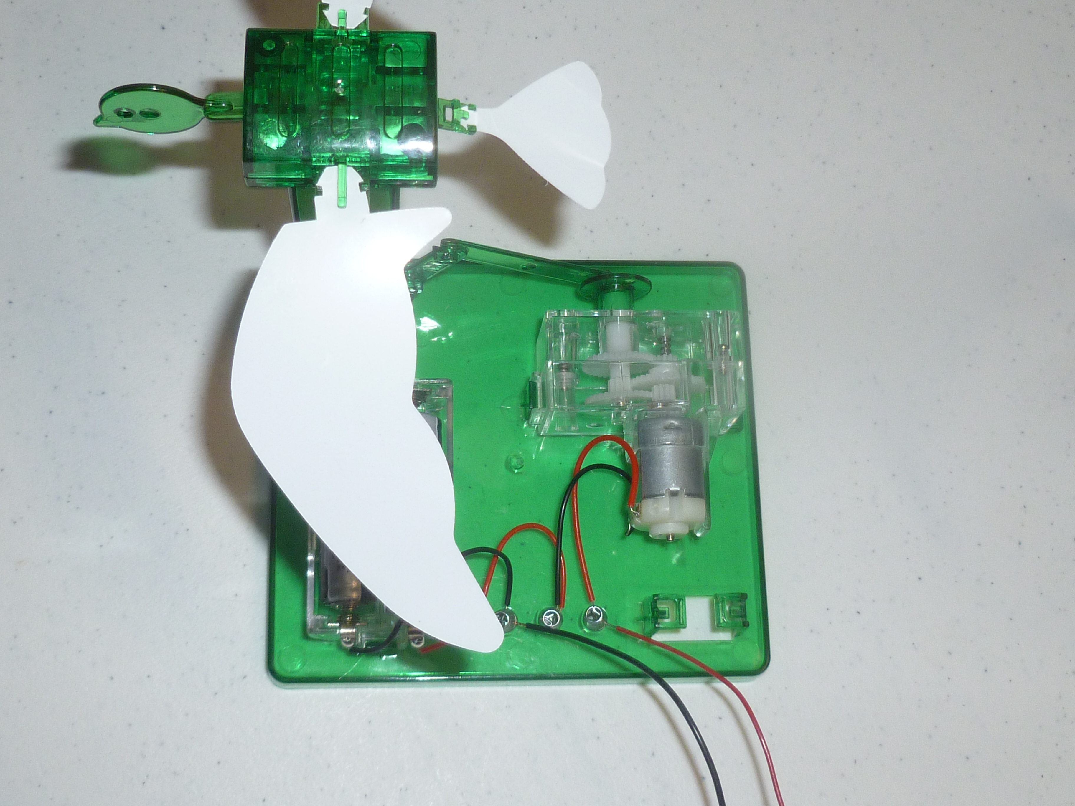
A few years ago in CSCI 255 we were able to control a few flapping birds from a PIC.
Unfortunately, the cheap plastic wings couldn’t take the stress.
The op amp
The LM386 is a low voltage audio power amplifier that is used in many audio devices, such as the Smokey® Amp. In fact, the Smokey Amp is little more than an LM386 with a couple of capacitors.
Take a look at the schematic in the upper left corner of page 5 of the LM386 datasheet which alos appears on the Audio Power Amplifiers with LM386 page of Hobby-Hour.com.
Try to build this on your breadboard. It’s only one potentiometer, one resistor, and a couple of capacitors. Be sure to power the LM386 from your battery holder.
This setup won’t be any louder than the 3904 amplifier,
but it can amplify very weak signals through a high resistance channel,
such as the 4M Ω human body.
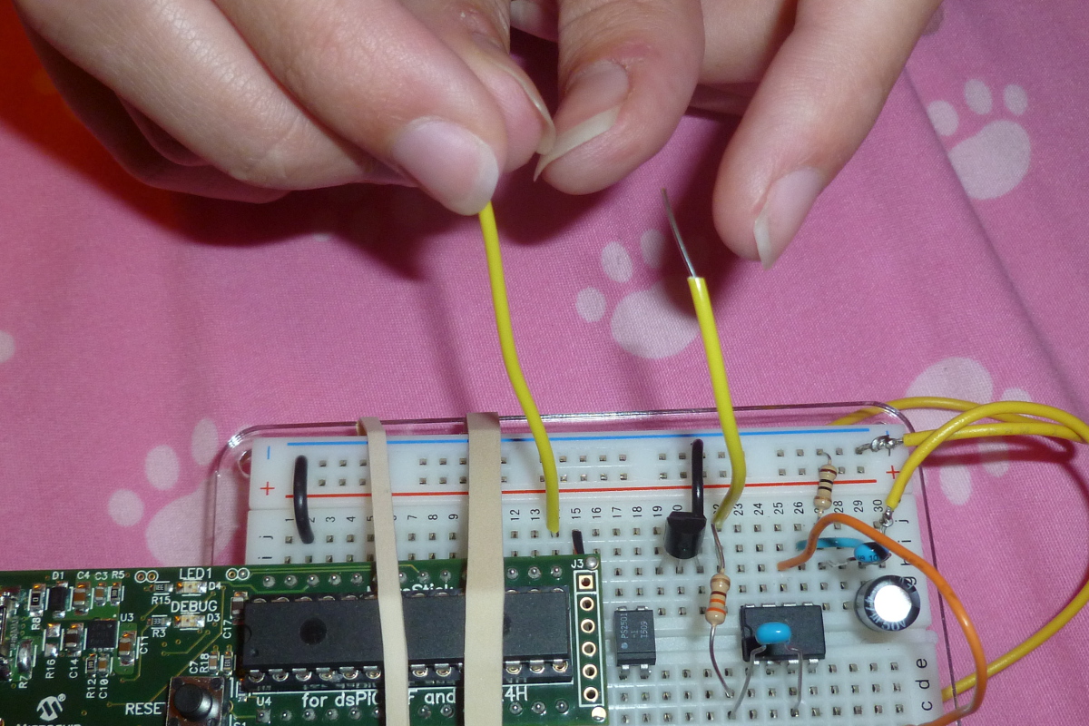
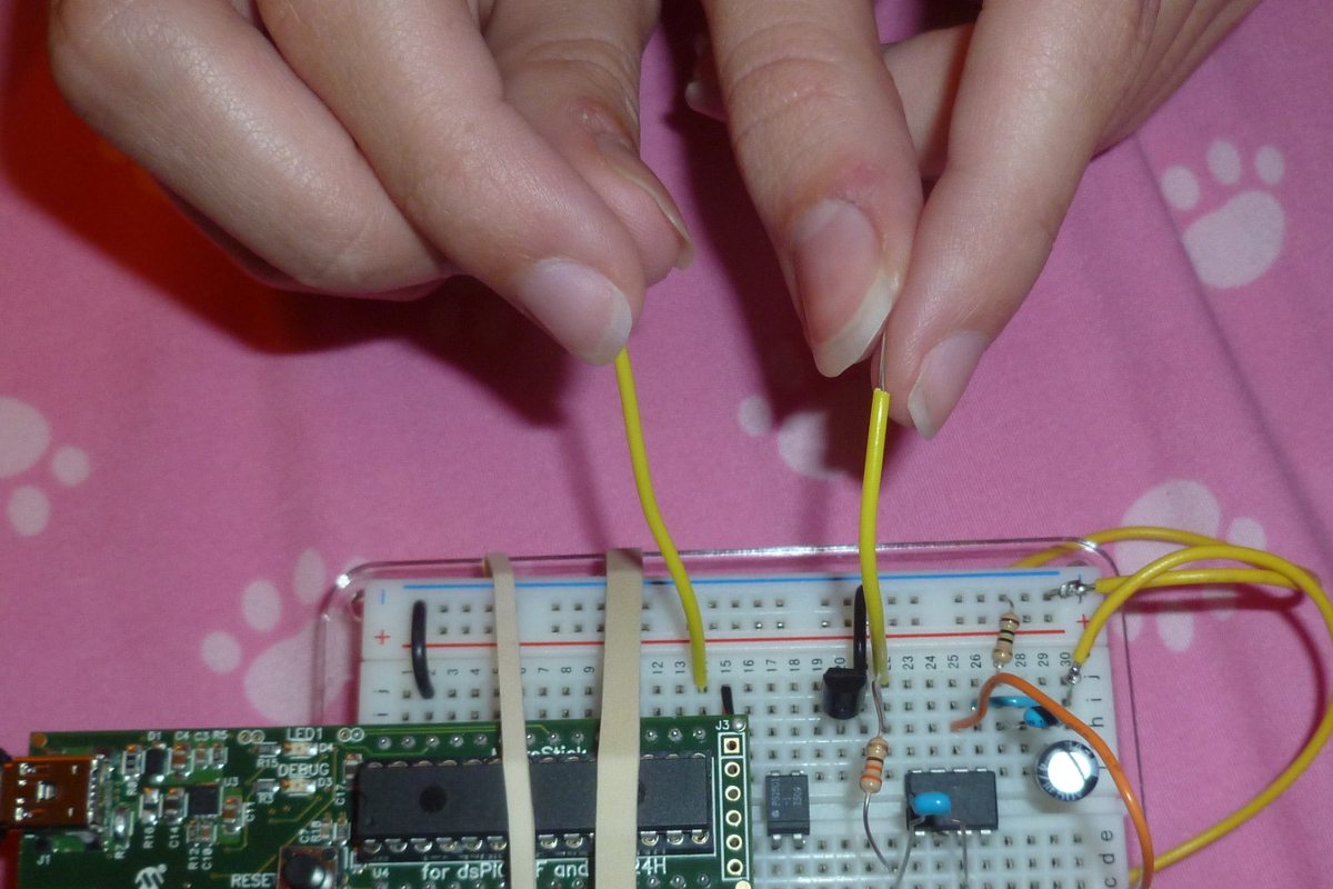
Here’s an example of a four-digit device
opening and closing the circuit.
I suspect this would work even if the entire class held hands to complete
the circuit, but this is a Computer Science class.
The PIC only produces 3.3 v. Do not try this at home
with the speaker wires coming out of your
200 watt stereo amplifier.
If you try this one, you will need a lots of parts.
The I2C controlled class-D amp
We have a few 2.8W class D amplifiers that will fit in a breadboard. We haven’t tried them out yet.