Getting ready
You’ll need the follow hardware for this lab.
- One red LED
- One yellow LED
- One green LED
- One 270 Ω resistor network
- One push-button switch
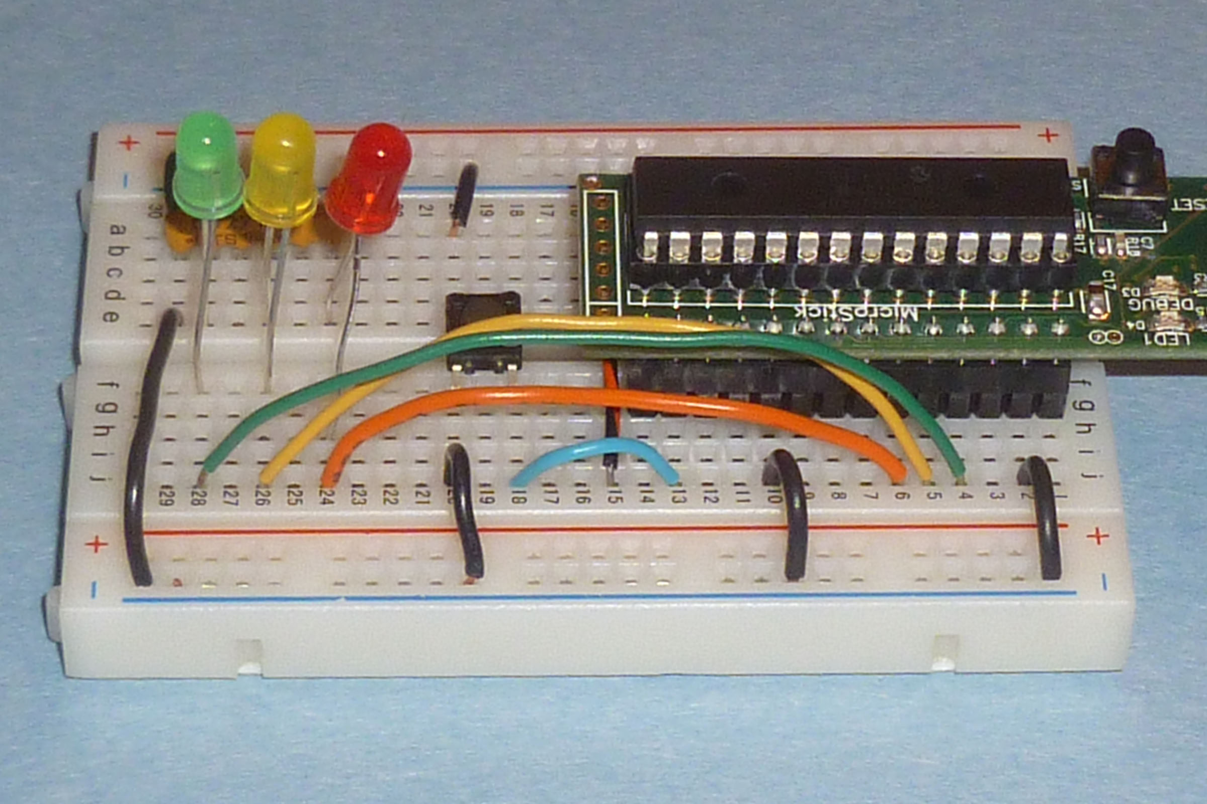
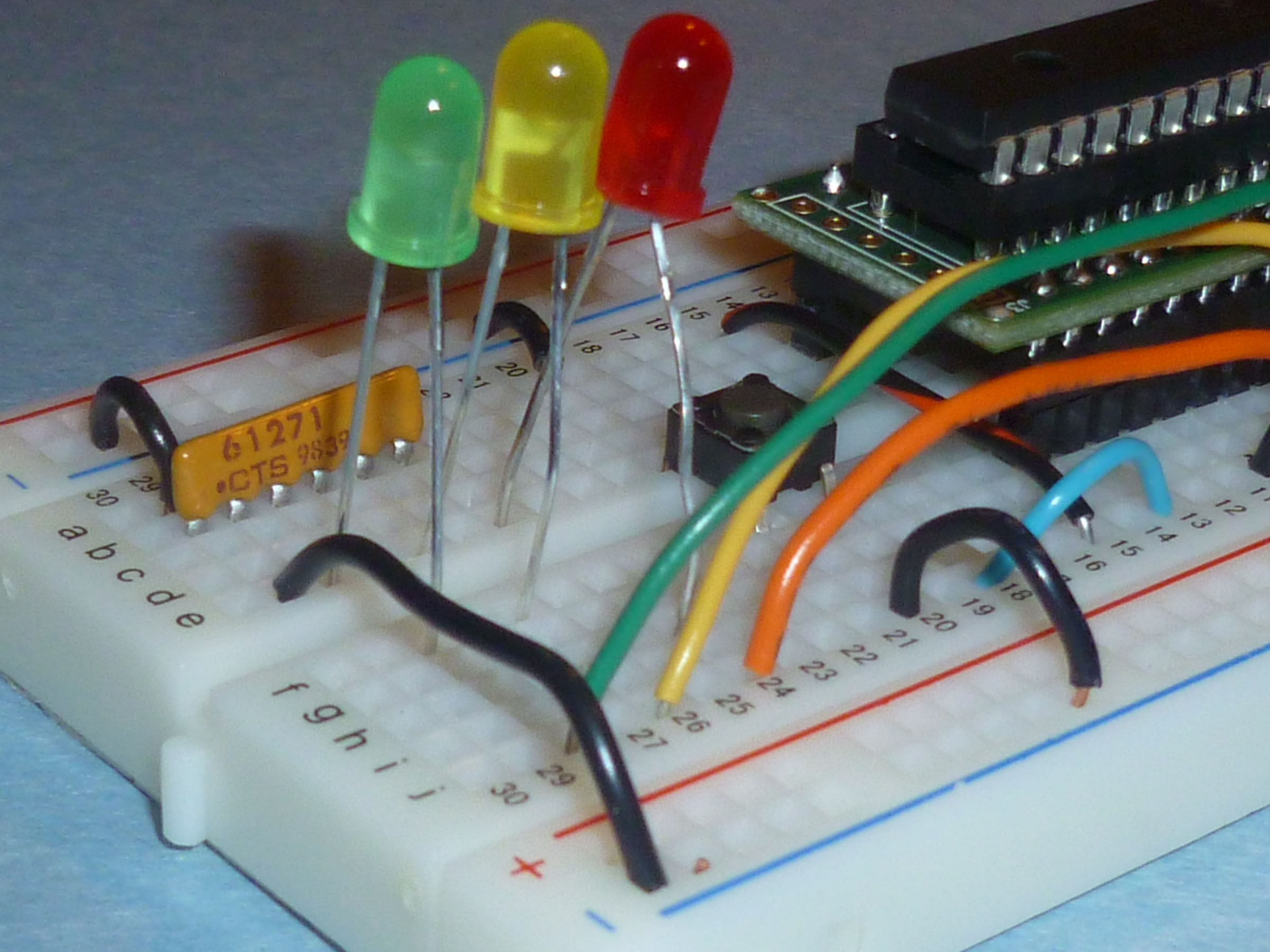
In order to keep consistency in our system setups during the lab, we are going to ask you to connect these devices to your Microstick as follows:
- Pin 25 (
RB14) to the green LED - Pin 24 (
RB13) to the yellow LED - Pin 23 (
RB12) to the red LED - Pin 16 (
RB7) to the push-button switch
If you place the PIC on the breadboard like we did in the PIN I/O on the PIC lab, the pins used in this lab will be in the f to j side of the breadboard. Remember, that the sum of the Microstick pin and breadboard row number will be 29 in the f to j side.
The
bussed resistor network contains five 270 Ω resistors in a single
SIP, serial inline package.
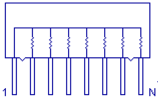
The pin of the resistor network right below the small black dot should be
connected to ground.
The cathode (-) ends of the LED’s to be
connect to the other pins of the resistor network.
Each LED gets it own pin.
The Microstick should then be connected to the anode (+) ends of the LED.
Note that no connections are made to the power (+) rail.
Finally, one side of the push-button switch is connected to ground; and the other side, to the Microstick.
We’d really like for you to figure out how to wire up your board from our prosaic description. However, we do offer a couple of pictures to help you check out your work.
A simple flashing light
Create a new MPLABX standalone project with the following as its C main file:
#include <stdlib.h>
#include <stdint.h>

// Contains definitions needed for pin I/O
#include <xc.h>

// Friendly names for the pins
// Sets the direction of pin, set to 1 if input
#define REDLEDTRIS   _TRISB12
// Sets the value written to an output pin
#define REDLEDVALUE  _LATB12

// You will need to tune this one
#define LOOPSPERMSEC 255

// This routine should waste m msecs
void waitmsecs(uint16_t m) {
   uint16_t msecCountDown ;
   uint16_t loopCountDown ;
   for ( msecCountDown=m; --msecCountDown; ) {
      // This inner loop should take 1 msec
      for ( loopCountDown=LOOPSPERMSEC; --loopCountDown; ) ;
   }
}

// For the first few labs use this to initialize the PIC pins
void usual255setup(void) {
   AD1PCFGL = 0xFFFF ;    // Set all pins for digital
   CNEN1 = 0 ;            // Disable change notification
   CNEN2 = 0 ;
   CNPU1 = 0 ;            // Disable weak pullup
   CNPU2 = 0 ;
   ODCA = 0 ;             // Disable open drain
   ODCB = 0 ;
   TRISA = 0 ;            // Set all pins for output
   TRISB = 0 ;
}

int main() {
   usual255setup() ;
   REDLEDTRIS  = 0 ;
   REDLEDVALUE = 0;
   while (1) {
      waitmsecs(7000) ;
      REDLEDVALUE  = !REDLEDVALUE ;
   }
   return (EXIT_SUCCESS) ;
}
A few things to notice about this program
This program does not use the functions defined in the textbook. It is simple PIC C code.
The function waitmsecs is a delay loop.
It does nothing except take its time doing nothing. The innermost loop of this routine is supposed to delay 1 millisecond, but really doesn’t.
The variable REDLEDTRIS is set to 1
(1 looks like a ’I’) when the red LED pin is used for input
and is set to 0 (0 looks like a ’O’) when
the red LED pin is used for output.
Setting the variable REDLEDVALUE to 1
sends a high voltage to the red LED
and setting REDLEDVALUE to 0 sends a low voltage to the LED.
Technically REDLEDTRIS and REDLEDVALUE are
not variables. They are preprocessor identifiers.
Because it would be difficult to remember that the red LED is associated
with _TRISB12 and _LATB12, C preprocessor
#define’s are used to create convenient names
REDLEXTRIS and REDLEDVALUE
for managing the red LED.
(We are following the C/C++/Java convention of using identifiers
with all capital letters for constants.)
And, by the way, _TRISB12 and _LATB12 are
also preprocessor identifiers to,
respectively, TRISBbits.TRISB12 and
LATBbits.LATB12 .
When you say REDLEDVALUE, the C compiler hears
LATBbits.LATB12 .
The function usual255setup initializes the output pins.
The reason for using these initializations was discussed in the
PIN I/O on the PIC lab.
We are trying to make the LED flash on or off every second. Time the flashing and see if this really is the case.
It isn’t. Adjust the #define for
LOOPSPERMSEC to tune waitmsecs.
Using the standard PIC delay function
One of the standard PIC24 C libraries has a routine __delay_ms
that can replace waitsmsecs.
(In C and C++ variable and function names starting with underscores should only be created by the compiler writers. This one even starts with two underscores!) In order to use __delay_ms, the programmer must first
define FCY, the number of instructions per second,
one-half the chip clock frequency.
The compiler can’t reliably determine FCY since you
could be using an external crystal to generate the clock.
You must define FCY and then include
the file libpic30.h in order to use
__delay_ms.
By default, your chip is being clocked by the FRC, the
fast resistor/capacitor which has a frequency of 7.34 MHz.
Add the following two lines after the #include of
xc.h to allow the use of
__delay_ms in your program.
#define FCY (7370000UL/2)
#include <libpic30.h>
Note the UL in your definition.
This causes 7370000 to be treated as an unsigned long.
If you omitted the UL, 7370000 would be treated as an integer, which is stored as a 16-bit twos-complement number on the PIC24.
Delete the waitmsecs function and replace calls of
waitmsecs with calls to __delay_ms.
You also might want to speed up those delays.
Seven seconds is a long time.
Now is your chance to demonstrate your binary arithmetic, file searching, and C savvy by answering the following three questions.
- What is the value of 7370000 when it is truncated to a 16-bit signed integer?
- What is the name of the function that is really called when you
“call” the C macro
__delay_ms? - What is longer than an
unsigned long?
You may need a Linux guru to help you with the second question.
Saving power
We really don’t need a chip executing 3685000 instructions per second to flash an LED every couple of seconds.
That’s a waste of power and possibly battery life.
Chapter 6 has a long discussion of how to change the clock rate
to save power, and we’ll apply a bit of it here.
We’re going to save power by using the LPRC (Low Power RC) as a
clock source in our flashy application.
Although you can change the clock source while the program is running,
we’re going to use a C
pragma
to set the IESO,
Internal External Switch Over,
and FNOSC, Initial Oscillator Selection Configuration,
fields.
These are both stored in configuration registers used
to set chip parameters before the chip is actually started.
This is done by placing the following lines at the beginning of your program.
#pragma config FNOSC=LPRC
#pragma config IESO=OFF
Names of other configuration pragma settings can be found by loading the file docs/config_index.html from your Microchip XC compiler installation. (The link will only work at your UNCA CSCI workstation.)
See if your circuit works just as well at this low power setting.
If you program your chip by changing only these lines, you’ll have to wait a long time for the LED to change. You better change the definition of FCY to reflect the nominal 32768 Hz frequency of the LPRC, unless you want to spend four minutes waiting for the the LED to change. Take note that not only is 32768 equal to 215, but 32768 Hz is the internal frequency of most quartz watches.
Green, Yellow, and Red
Let’s modify your program so that its looks like a real
traffic signal.
Start by
making some useful #define’s for the green
and yellow LED’s. Remember, RB14 is connected to the
green LED; and RB13, to the yellow LED.
Modify the while loop of the
main routine so that it cycles through all three lights.
The yellow light doesn’t stay on as long as the green or red lights.
The fire truck button
We want to add the button to our application.
This is 50% more complicated than the LED’s, because
we must enable the pull-up on the push-button.
Start by placing the following
#define’s near the beginning of your program.
// Sets the direction of pin, set to 1 if input
#define BUTTONTRIS   _TRISB7
// Returns the value read on an input pin
#define BUTTONVALUE  _RB7
// Sets the internal pull-up (it really is 23, RB7 is also CN23)
#define BUTTONPULLUP _CN23PUE
You also need to add some code after the call to
usual255setup
to enable the pull-up and set the button to input mode.
With the pull-up enabled, BUTTONVALUE will be 0 when
the button is pressed and 1 when it is not.
   BUTTONTRIS = 1 ;
   BUTTONPULLUP = 1 ;
We want to implement “fire truck mode” for our light. Just pretend that the fire truck can remotely push the button to make the light flash the red and yellow bulbs at the start of the next cycle.
Modify your program so that when the button is pressed at the beginning of a cycle, the stoplight will perform a cycle of flashing the red and yellow LED’s on and off. If the button is not pressed, the stoplight performs the normal cycle.
You need to put an if else inside the
while to achieve fire truck mode.
Who let the dog out
You probably haven’t noticed this; but every 128 or so seconds, the watchdog timer is restarting your program. We’d like to use the watchdog timer to save energy by making our program spend most of its time sleeping.
The first step in accomplishing this is setting the length of the naps. This is done by adding even more pragmas at the beginning of your program.
#pragma config FWDTEN=OFF
#pragma config WDTPRE=PR32
#pragma config WDTPOST=PS1024
The first pragma actually disables the watch dog timer.
However, your program will be able to turn it on when it wishes.
The remaining pragmas determine the watch dog timer time-out period
for those times when the watch dog is on guard. In this case
the time-out period is set to 32×1024÷32768 seconds.
The 32 comes from the WDTPRE=PR32 pragma,
the 1024 comes from the WDTPOST=PS1024 pragma,
and 32768 Hz is the frequency of the low power FRC.
Since 32×1024÷32768 equals 1, we are set up
for one second naps.
Because it would hard to explain all the steps needed to take a nap, we are just going to give you a function that performs some short naps. Read the comments to figure out what is happening.
void snooze(int secs) {
   int i ;
   for (i=0; i<secs; ++i) {
       _SWDTEN = 1 ;                       // enable the dawg
       __asm__ volatile("pwrsav #0") ;     // It's PIC assembly in C!!!
              // in power save mode
              // wait here until the dawg barks
       _SWDTEN = 0 ;                       // disable the dawg
   }
}
Incorporate snooze into your program so that it
does nothing almost all the time.