We (UNC Asheville) have decided to make the move to the new MPLAB® X IDE even though the textbook still uses the older MPLAB 8. The MPLAB X software is NetBeans based and will run under Linux, Mac and Windows. The older MPLAB 8 only ran under Windows.
You can download your own copy of MPLAB X from Microchip’s MPLAB X download page. You will want a copy of the following:
- MPLAB X IDE – v1.90 is installed in the lab
- MPLAB XC 16 Compiler – v1.11 is installed in the lab
You can get a list of common instructions from the exam summary sheet. If you want to read 226 pages about MPLAB X, check out the MPLAB® X IDE User’s Guide. You will also find the 460 pages of the 16-bit MCU and DSC Programmer’s Reference Manual: High-Performance Microcontrollers (MCU) and Digital Signal Controllers (DSC) and the 278 pages of the MPLAB® XC16 Assember, Linker and Utilities User’s Guide to be useful.
Getting Started
From the command line you can type mplab_ide or you can use your mouse to run MPLAB IDE using the Linux menu selections Applications ⇒ Programming ⇒ MPLAB IDE. (Don’t choose MPLAB IPE.) It may take a little while to start when you first fire up.
MPLAB X is based on NetBeans. Your first menu should give you tabs with labels like:
- Learn & Discover
- My MPLAB IDE
- What’s New
You’ll find many links on this startup page to references about MPLAB X. Microchip also has a collection of MPLAB X Webinars, short (and inexpensively produced) videos about MPLAB X.
First Project in MPLAB X
Creating the project
Use the menu choices File ⇒ New Project... to begin the process of creating a project. Then work your way through a few windows.
- From the Microchip Embedded category choose a Standalone Project.
- Choose the 16-bit MCUs (PIC24) family and then select the device PIC24HJ64GP502, which will be near the end of the list. Next time you’ll be able to speed up this process by choosing the Recently Used family.
- Select the Simulator as your hardware tool.
- Select XC 16 as your compiler.
- Finally choose a project name, perhaps CSCI255lab0A and click Set as main project.
You may have noticed that many of selected choices were preceded by a little green dot. Avoid the ones with the red and yellow dots.
Let’s mention a couple of things before going on.
There were a lot of devices to choose from. If you are using the simulator, as we are today, you don’t have to be that precise in your selection, but usually you must choose the device the that matches the one you plan is use in your project.
The XC 16 is Microchip’s latest compiler for its 16-bit processors, like the PIC24. We are using the free (unlicensed) version. The free compiler is based on the gcc toolchain and it does not optimize your C code. It will cost you about $1000 to get the optimizing “PRO” compiler.
Also, notice that your projects are going to be stored in directories with names that end with a capital X, such as CSCI255lab0A.X .
Checking it out
At this point you have a NetBeans environment that will be familiar to the alumni of CSCI 181 and 202. Move your mouse over the menu choices at the top of the window, from File to Help. Press on the choices to look at their submenus. Pay particular attention to items under Debug. Most of the choices are presently grayed out, because they can’t be used until you are working on a project.
Notice that the lower left corner is occupied by a Dashboard display. The Microchip PIC devices have very little memory so we need an easy-to-use means of figuring out how much memory our programs are using.
Adding some assembler program
Now we’ll use the menu to create a assembler program. Right click on Source Files then New ⇒ Other... . (The lack of choice for assembler should give you some idea of how often assembler programs are written, even for a $3 microcontroller.) Again, let’s do some windows.
- From the Assembler category choose AssemblyFile.s . Be sure to make the .s choice.
- Choose a name for your file. I suggest something like whatever . MPLAB X will add the .s to your filename.
At this point, you should have an empty program in the upper-right window. Make sure that your program really is under Source Files.
Copy the following program into your empty window.
.include "xc.inc"
.global __reset
.bss
x: .space 2
.equ initX,255
.text
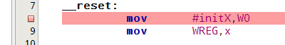
__reset:
mov #initX,W0
mov WREG,x
bigloop: mov x,W5
add W5,W5,W6
add W5,W6,W6
mov W6,x
inc x
bra bigloop
.end
Go ahead and press the hammer to built it, so we can make sure your installation is working.
This program is roughly equivalent to this segment of Java code.
short x = 255 ;
while (true) {
   x = 3*x + 1 ;
}
What’s it all about
But clearly this isn’t Java.
Let’s look at this program for a minute. Like most assembly language programs, this one contains several pseudo-ops or directives. These are lines of code that don’t create instructions. They may define space for variables or control the assembly process or even control the spacing for a printout of your code.
The program starts with the directive:
.include "xc.inc"
This causes the assembler to include a file defining useful constants
for programming PIC microcontrollers.
Just for the fun of it, open up the file
/opt/microchip/xc16/v1.11/support/PIC24H/inc/xc.inc in either MPLAB X or your favorite text editor.
(If you use MPLAB X, be sure to use
Open File... and not
Open Project... .)
That one isn’t interesting. It’s just a list of include files
for several different PIC processors. Try again, but this time open up
/opt/microchip/xc16/v1.11/support/PIC24H/inc/p24HJ64GP502.inc .
Go to line 1308 to find a definition we’ll use in a little while.
If you do serious system development, you’ll find yourself looking
at system files like these when things go seriously wrong.
We are serious. Look at that second file.
Now close those two big system files and get back to your program.
The second line in your program is also a directive:
.global __reset
This causes the assembler to announce
__reset as an external variable of your program.
This means that the outside “world” will know about
__reset.
In fact, __reset will be the address of the first instruction executed after a processor reset.
Since ancient times, running programs have been considered to consist of four segments:
(1) the text segment, which contains compiled code;
(2) the stack segment, which contains local variables used by functions or methods;
(3) the heap segment, which contains dynamically allocated memory, such as Java objects; and
(4) the data segment, which contains global variables. The data area also contains the oddly name bss (block started by symbol) segment which contains space for uninitialized data.
In this program, you see that both a bss and text segment are defined. The bss segment sets aside two bytes for the variable x.
The text segment contains the PIC instructions.
There is one more interesting directive in this program:
.equ initX,255
This one means that whenever your code says
initX, the assembler thinks 255.
This means that you can use #initX in place
of #255.
Executing a program
The Microchip simulator does know how to simulate the PIC instructions of your program, but all your program does is loop forever. To see anything interesting you must step through the program.
To do this you need to know how to set breakpoints in
your program.
Move your mouse onto the narrow column of program line numbers just
to the left of the first real instruction of your program
and click.
There should put a little red square in the line number column
and highlight the entire line in red to show that you have
set a breakpoint.
Now use the menu choices
Debug
⇒
Debug Project. This should start the
simulation but stop at the breakpoint.

Put the break in your program and run your program to the breakpoint. If you have done this before using NetBeans, help out any lab neighbors who haven’t.
You will notice a bunch of new tabs in the lower right panel.
We want to add one more.
Use the window menu choices
Window ⇒
PIC Memory Views
⇒ SFRs
to bring up a new tab called SFR
which will display the registers of the PIC.
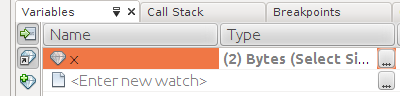
Also, go over to the Variables tab
and add a watch for the variable x.
You should see x next to a little diamond.
(At least I think it’s a diamond.)
Right-click on this entry and change its display type to decimal.
Press the F8 key to step through your program.
Switch between the
SFR and
Variables tabs to see the current
values of x, W0, W5 and
W6.
To end your debugging session, you can press the little x
on the right lower edge of the screen or type
SHIFT+F5.
Step through your program until the variable x is
between 4000 and 50000. If you pass it once, just keep trying.
It will overflow and come around again.
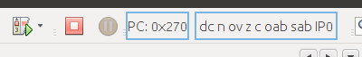
Checking status
If you look at the upper left of your window, you’ll see a box
with odd “words” like dc,
n or
Z.
These are the process status bits. They keep up with that
happened during the last PIC operation.
Halt your present debugger session and start another.
Step through your program until x has the value of
20695.
This will require four loops.
Look at the PIC status display. You will see
n,
ov,
z
and c, all lower case.
These indicates that the
N,
OV,
Z and
C bits of the
PIC status register
are all off.
However, that is about to change.
Press F8 until you reach the instruction
labeled bigloop.
Then one more F8
to arrive at the first ADD instruction of the loop.
Bring up the SFR tab.
Your program is about to add W5 to itself.
20695+20695=41390, but the largest positive number that can
be stored in 16-bit twos-complement is 32767 or 215-1.
This register is about to go negative which means there will be
an overflow.
At this point, you might be better off looking at the
binary display of the register values because the
decimal display is purely unsigned.
In binary we are adding
0101 0000 1101 0111
to itself. The result will be
1010 0001 1010 1110,
which is negative in twos-complement.
Go ahead and execute the instruction. You’ll see
N and OV
in the status register display.
Indeed the value of W6 is
0101 0000 1101 0111.
Two positive numbers have been added and result in a negative number.
An overflow has occurred.
Now step through the next instruction. This time the processor
is adding
0101 0000 1101 0111 to
1010 0001 1010 1110.
You never get an overflow when adding numbers of different signs, but
here you will get a negative number
1111 0010 1000 0101.
You’ll see
N and ov
in the status display.
Let’s do one more addition.
Use F8 to get to the next add.
This time we are adding
1111 0010 1000 0110
to itself.
The result will be
1110 0101 0000 1100.
The result will be negative, so there is no overflow.
However, there is a carry as is always the case
when adding negative numbers. The status bits are
N, ov
and C.
Were you careful enough to get N, ov and C?
Trying out arrays
This times it’s an abbreviated description. Create a MPLAB X project that contains this program.
          .include  "p24Hxxxx.inc"
          .global   __reset
          .equiv    vSize,100
          .bss
i:        .space    2
j:        .space    2
V:        .space    2*#vSize
x:        .space    2
ugh:      .space    2
          .equ      initX,255
          .text
__reset:
;;; initialize V to the first 100 square numbers
          mov       #vSize,W5       ;; countdown
          mov       #V,W6           ;; pointer into the array
          clr       W7              ;; evolving square
          mov       #1,W8           ;; odd numbers
initloop:
          mov       W7,[W6++]       ;; moving W7 to elements of V
          add       W7,W8,W7        ;; W7 will be 0, 1, 4, 9, ...
          inc2      WREG8           ;; w8 will be 1, 3, 5, ....
          dec       WREG5           ;; W5 will count down from 100
          btss      SR,#Z           ;; skip next instruction when Z set
          bra       initloop

brkpnt:   mov       x               ;; just a place to put a break point

;;;     x = V[15] ;


;;;     V[17] = -17


;;;     i = 33
;;;     x = V[i]

;;;     j = 53
;;;     V[j] = -19

;;;     x = V[i+5]

;;;     V[i+j] = -23


bigloop:
          bra       bigloop
          .end
Here are some things worth noting.
- Constants, such as
Vsize, can be used in constant expressions, such as2*#Vsize. - The
btssinstruction can skip the next instruction if a particular bit, such as theZbit, is set. This is the old way of controlling loops.
You might also look at the code for initializing an array of 100 integers to the first 100 squares.
What you are supposed to do
There are five comments containing short sequences of C/Java code after the loop. See how many of these you can complete.