This lab is to help you get started on Project 10.
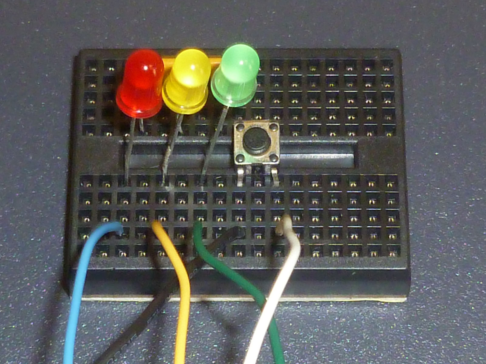
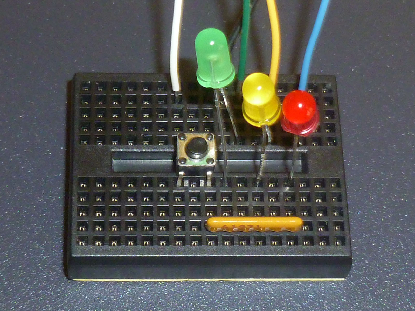
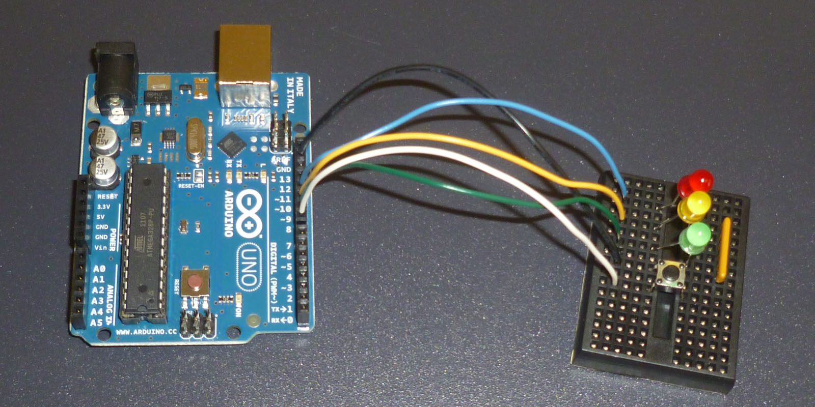
Here is some pictures of a minimal hardware setup.
The light brown component is a bussed resistor network SIP.
If you don't have one of these, you'll need to use three separate resistors.
The black wire connects one side of the push button switch to ground on the Arduino. On the other side of the breadboard trough, that same side of the push button is connected to the common pin of the resistor network.
#define REDBULB     11
#define YELLOWBULB  10
#define GREENBULB    9
#define SWITCH       8
  pinMode(REDBULB,     OUTPUT) ;
  pinMode(YELLOWBULB,  OUTPUT) ;
  pinMode(GREENBULB,   OUTPUT) ;
  pinMode(SWITCH,      INPUT)  ;
  digitalWrite(SWITCH, HIGH)   ;