In addition to the power supply that you created on your breadboard in Lab 3, you will need the following equipment and components to complete your PIC prototype board:
In this lab, you will build a prototype PIC system on your breadboard and test it. You'll begin by modifying the 3.3V power supply that you built on your breadboard in Lab 3.
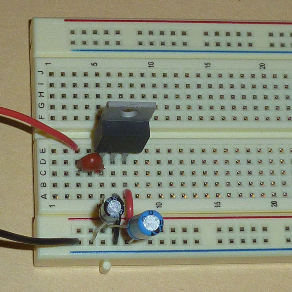
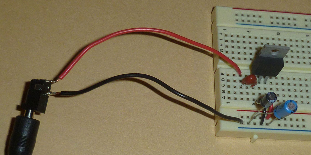
The voltage supply circuit that you built in Lab 3 is depicted below.
If you circuit does not look like this one, return to
Lab 3 and fix the problem.
Some of you may have “lost” your fuse and have replaced
it with a wire.
It's important replace the fuse, and any missing components,
for the final PIC system you are creating today.
Once your starting configuration matches that shown above, it’s time to augment it. Throughout this lab, try to use black wires to connect to the ground rail and red wires to connect to the power rail. Thus will make the lab easier for you and your instructor.
Locate the power connector and wall transformer shown below.
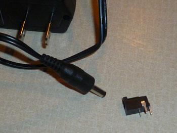
If you are lucky, you will find a power connector with wires soldered
to its leads. In that case you can skip the next step.
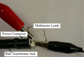
If you aren't lucky,
plug the power connector into the wall transformer and use your multimeter to determine which two pins on the power connector provide +6V and ground as shown below. Each power connector has three leads, but only two are used.
Solder wires to the power connector.
Connect a black wire to the ground pin and a
red or orange wire to the +6V pin.
The ground wire is then connected to the ground rail and
the +6V lead connects to the resettable fuse.
Use the multimeter to verify that you are receiving 6 Volts of power at the connections to the breadboard before proceeding.
The input power switch allows you to isolate your system from the wall transformer without disconnecting wires. Our switch is a single-pole double-throw (SPDT) slide switch. In an SPDT switch, a pole is always connected to one of two throws. If you have an overhead light at home that can be turned on and off from two locations, you have a couple of SPDT switches.
Connect the input power from the power connector
to one of the outer pins of the switch and connect
the fuse to the pole.
Pay attention to the wiring of the switch.
The power switch can be a little confusing. It appears to spread
across five breadboard columns; however, it only has three pins.
The center pin is the pole, and it must be connected to the
resetable fuse. The other two pins are the throws. In the
picture above the power supply is connected to the leftmost throw.
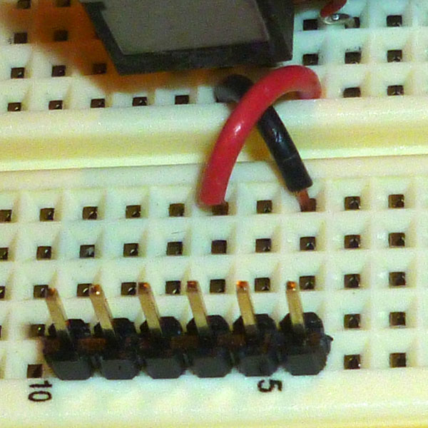
As our final modification to the power supply, we'll connect
a 6-pin header to the board and wire it to the power switch
and to ground as shown below.
Note that the red wire is connected to the other throw
of the switch.
You should also go ahead and temporarily connect the
FTDI TTL-232R-3.3V USB-to-serial cable to the 6-pin header.
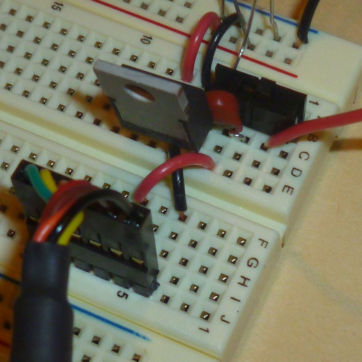
Make sure that the connector is turned so that the black wire
of the USB cable is connected to ground on your voltage regulator.
If you are
using black wires for ground and red wries for power, the cable will
match your wiring.
Now you can verify that your power supply is working by moving the switch between your two power supplies, the power connector and the USB cable. You will need to use the multimeter to determine that power is being provided from both sources. (Alternatively, you can add an LED and resistor to your circuit for a minute of two.)
When you pull the cable off your circuit, the 6-pin header may stay attached to the cable. This isn't a problem if you always plug in the cable so that the ground wires match.
| Show your breadboard power supply to your instructor. |
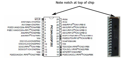
The PIC24HJ32GP202 processor is shown below. Note that each pin has a function and that the pins are numbered counter-clockwise with
Pin 1 being to the left of the notch on one end of the chip.
Pins are also given names. Some names are simple:
VDD
is power, and
VSS
is ground.
However, most pin have multiple functions
and are known by complicated names, such as
PGED2/TDI/RP10/CN16/RB10.
Fortunately, these pins usually go by shorter names, such as
RP10, that correspond to their use
with a particular application.
260 pages of detailed information about the PIC processor
can be found in its product datasheet.
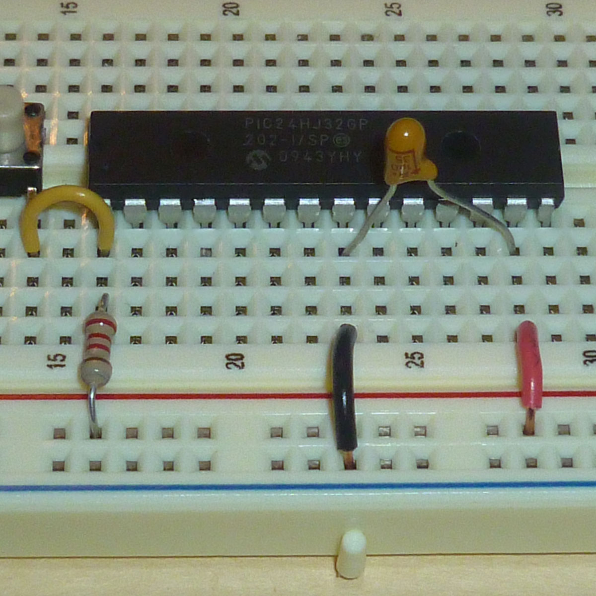
Our next objective is to place the PIC processor on our breadboard and create the connections described pictorially below. Follow the itemized steps below to create this configuration on your breadboard.
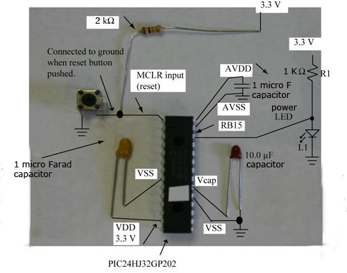
First, identify the top of your PIC microcontroller. With the top of the PIC orientated towards the power supply, place it across the trough of your breadboard. Leave eight to ten breadboard columns between the voltage regular and the PIC processor.
Second, find your pushbutton switch and use a multimeter to determine the pins that connect when the pushbutton is pressed. The other two pairs of pins are permanently connected together.

Third, place the pushbutton switch on your breadboard so that it spans the trough between connected rows. It should be positioned between the power supply and the PIC microcontroller, perhaps a couple of breadboard colums away from the PIC. This switch will be the reset button for your computer.
Fourth, make a connection between the PIC
MCLR
pin (Pin 1) to
the reset switch. Also, connect
MCLR
to the power rail with a
2.2 kΩ resistor. Finally connect the other side
of the reset button to the ground rail.
MCLR
is grounded when the button is pushed.
Otherwise, it is 3.3V.
Fifth, to smooth out voltage fluctuations on the breadboard,
a decoupling capactor is placed between the
VDD
and
VSS
pins.
Connect your 1 µF capacitor between
VSS
(Pin 8) and
VDD
(Pin 13).
This capacitor is polarized.
The longer leg of the capacitor, which is also marked
with a + sign, must be connected to the
VDD
pin (Pin 13).
The shorter leg is connected to
VSS
(Pin 8).
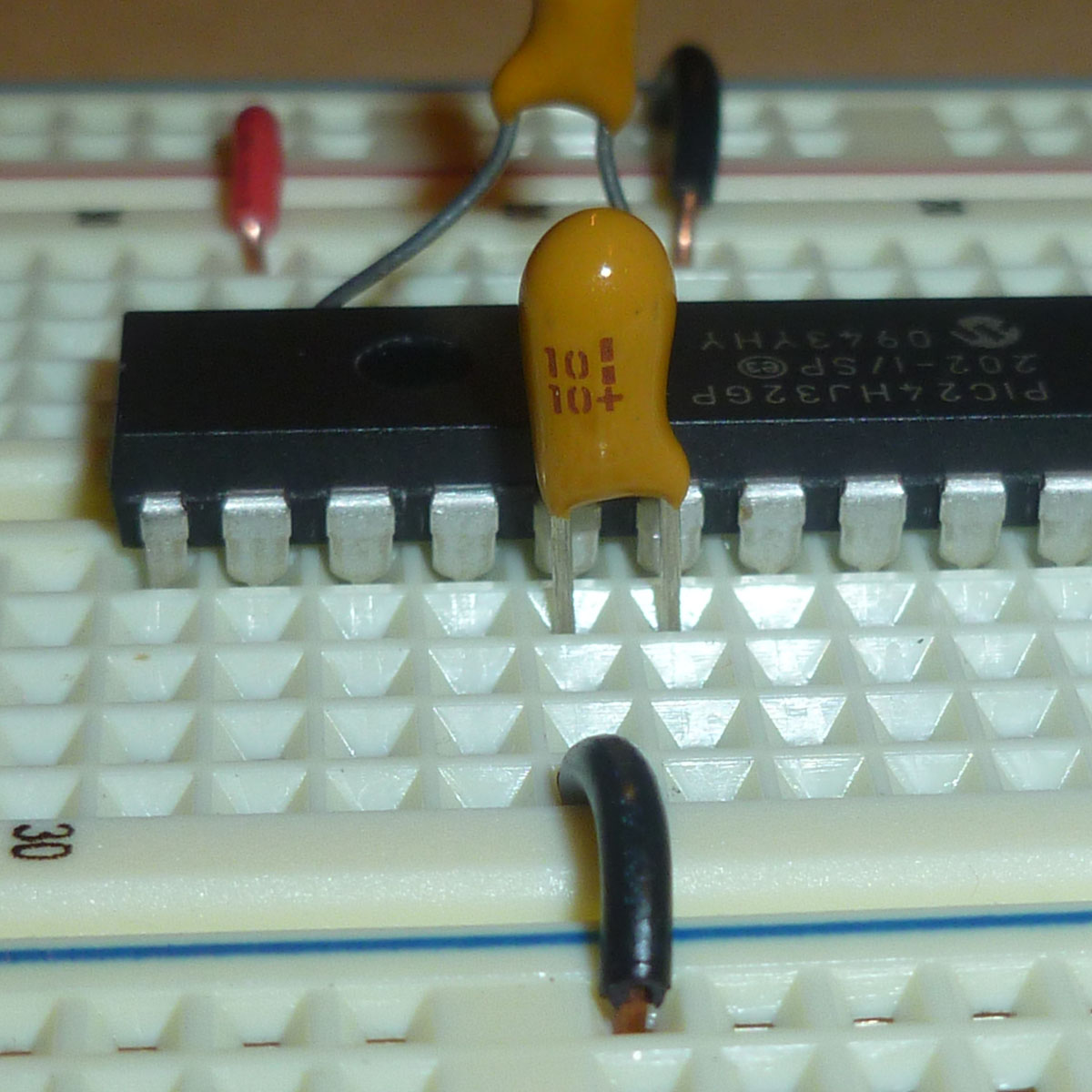
Sixth, the PIC processor needs an additional capacitor
to stabilize its own internal voltage regulator.
This is a 10 µF capacitor placed between
VCAP/VDDCORE (Pin 20)
and the other
VSS
(Pin 19).
As before, the capacitor leg without the + sign is connected to
VSS
(Pin 19).
Connect
VCAP/VDDCORE (Pin 20)
only to the +-signed leg.
Do not connect
VCAP/VDDCORE to the power rail!
Seventh, there is one more decoupling 1 µF capacitor.
This one is for power to the analog modules within the PIC processor.
This capacitor goes between
AVDD
(Pin 28) and
AVSS
(Pin 27).
Once again, place the leg with the + sign to
AVDD.
Then connect
AVSS
to the ground rail and
AVDD
to the power rail.
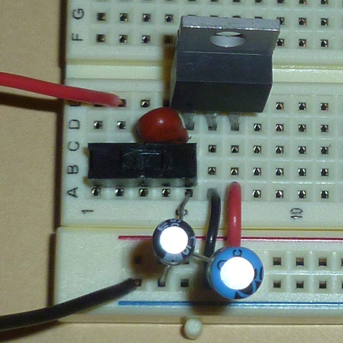
Now that your capacitors are connected,
it would be a good time to make sure your wiring resembles the
following picture.
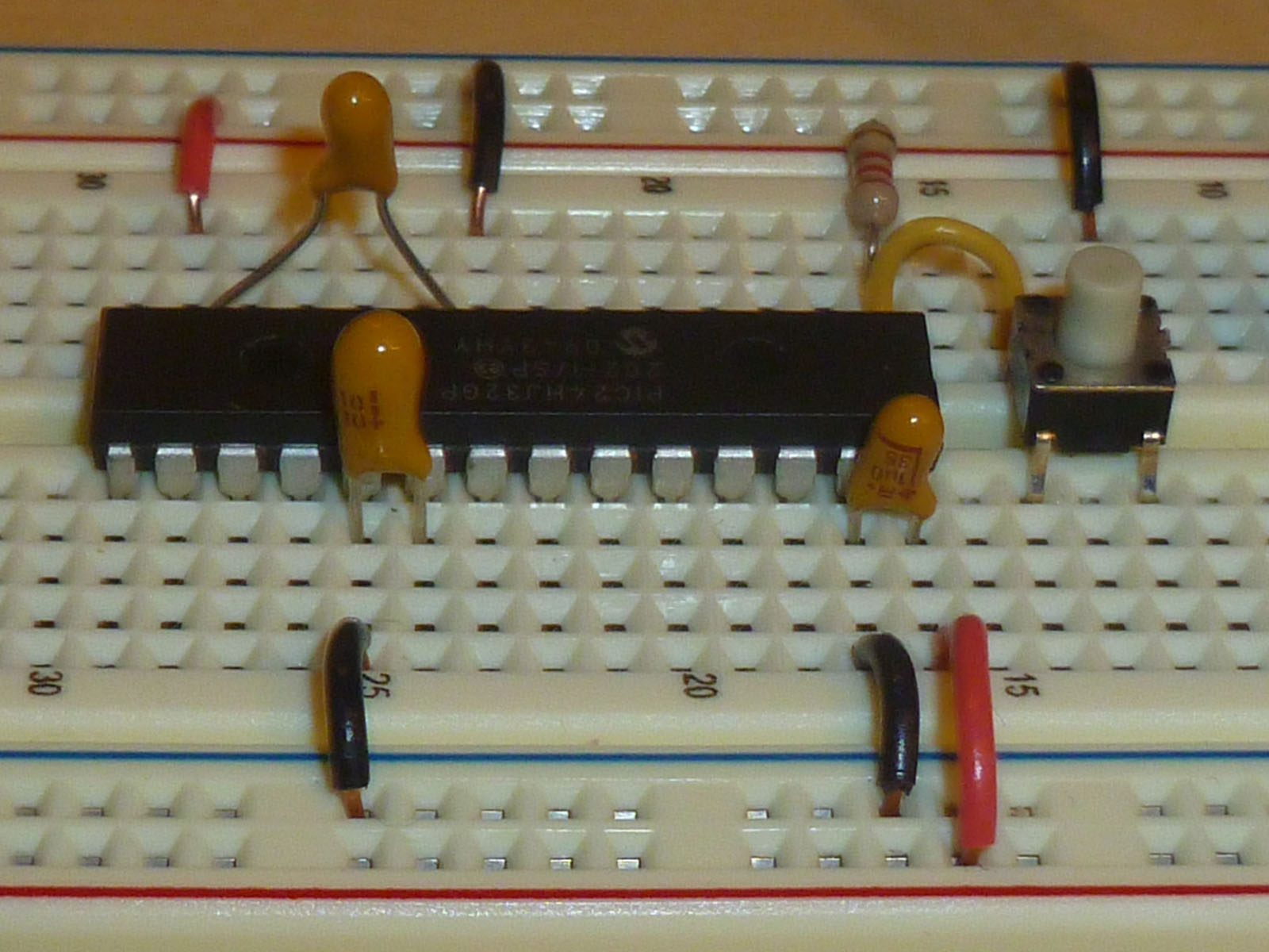
| Show your board to your instructor. |
Eighth, connect the 6-pin header for the
USB cable connection to the chip.
When the cable is properly attached, the first pin of the header is
GND and the third is
VCC.
The cable’s VCC is 5 volts
and the PIC processor’s
VDD
is 3.3 volts.
The two should never be directly connected!
The sixth pin (furthest from ground) of the header is
RTS# and should be connected to
MCLR
(Pin 1) of the PIC.
It’s a little easier to run the wire between the sixth pin
and the half of the reset button that is already
connected to
MCLR.
The fifth pin of the header is
RXD and should be connected to
RP11
(Pin 22) of the PIC.
Finally, the fourth pin of the header is
TXD and should be connected to
RP10
(Pin 21) of the PIC.
It really doesn't look as bad as it sounds.
It's only three parallel wires.
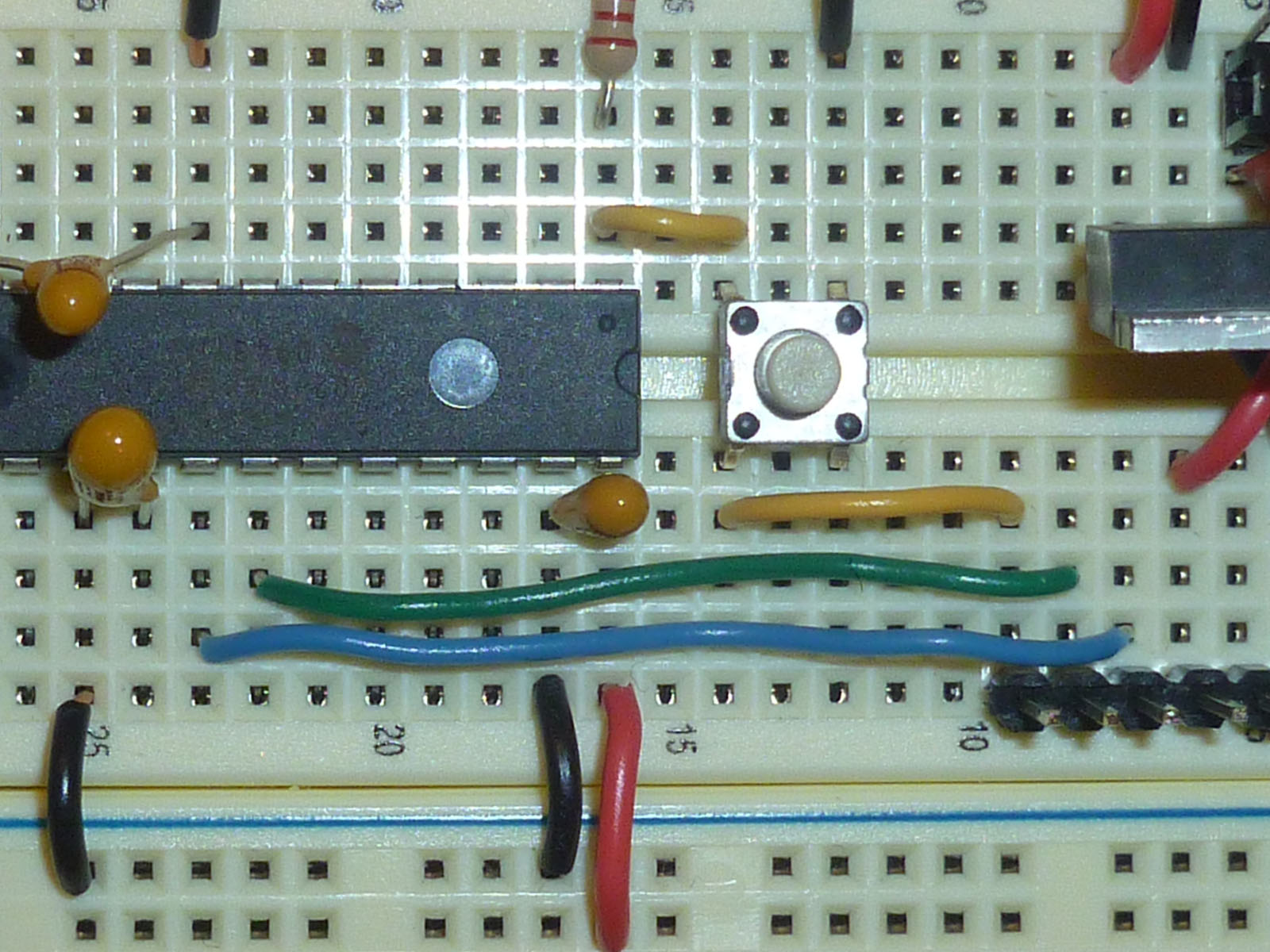
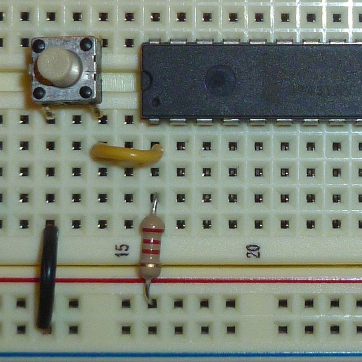
Ninth and last, we’re going to place an LED on
RB15 (Pin 26) of the PIC.
The software provided by the textbook authors should flash
this pin if your program is downloaded correctly.
Make this connection by placing a 910 Ω (or 1 kΩ)
resistor between
RB15 (Pin 26) and the power rail.
Then place a LED between
RB15 (Pin 26) and the ground rail.
Be sure the LED is turned in the right direction.
It should look something like the following picture.
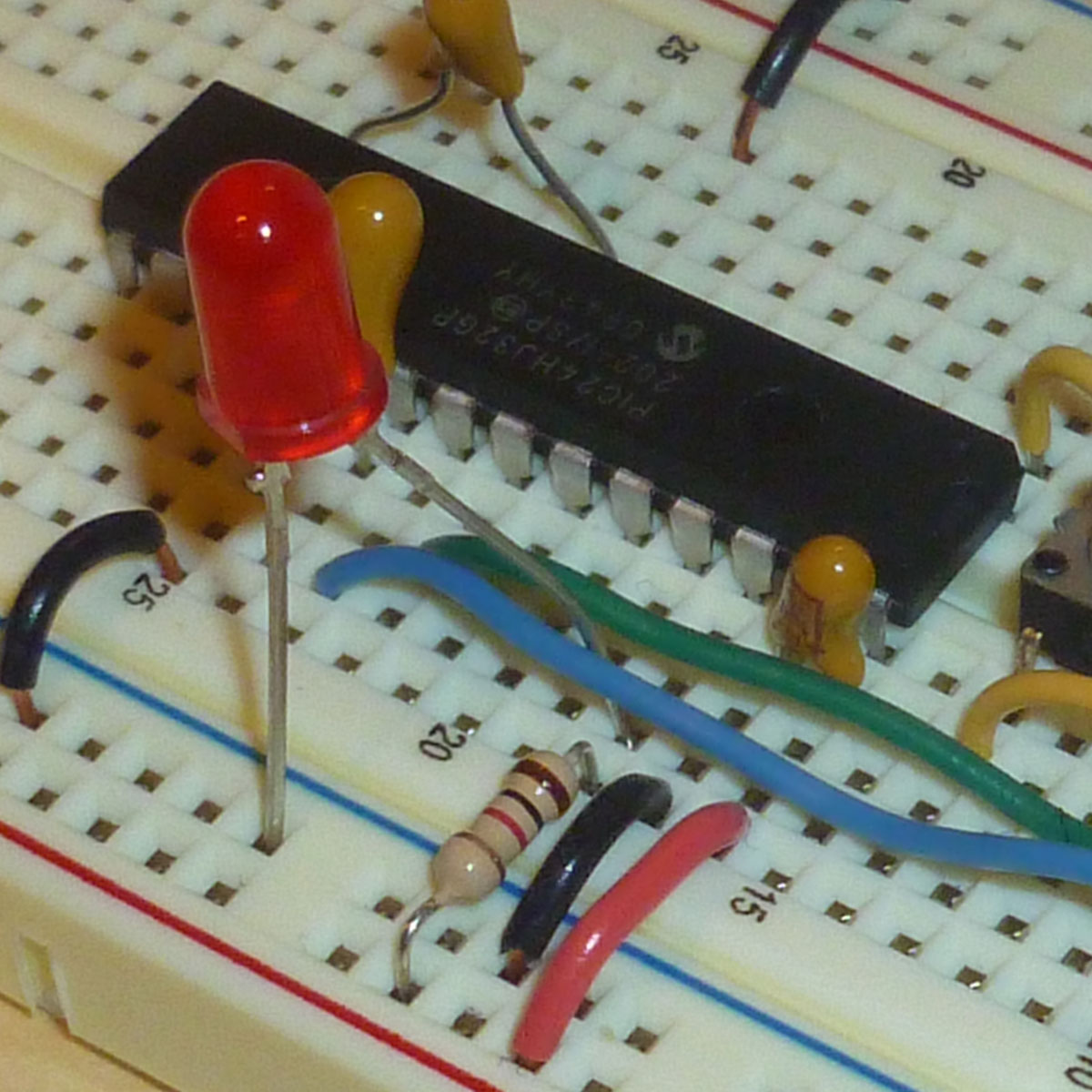
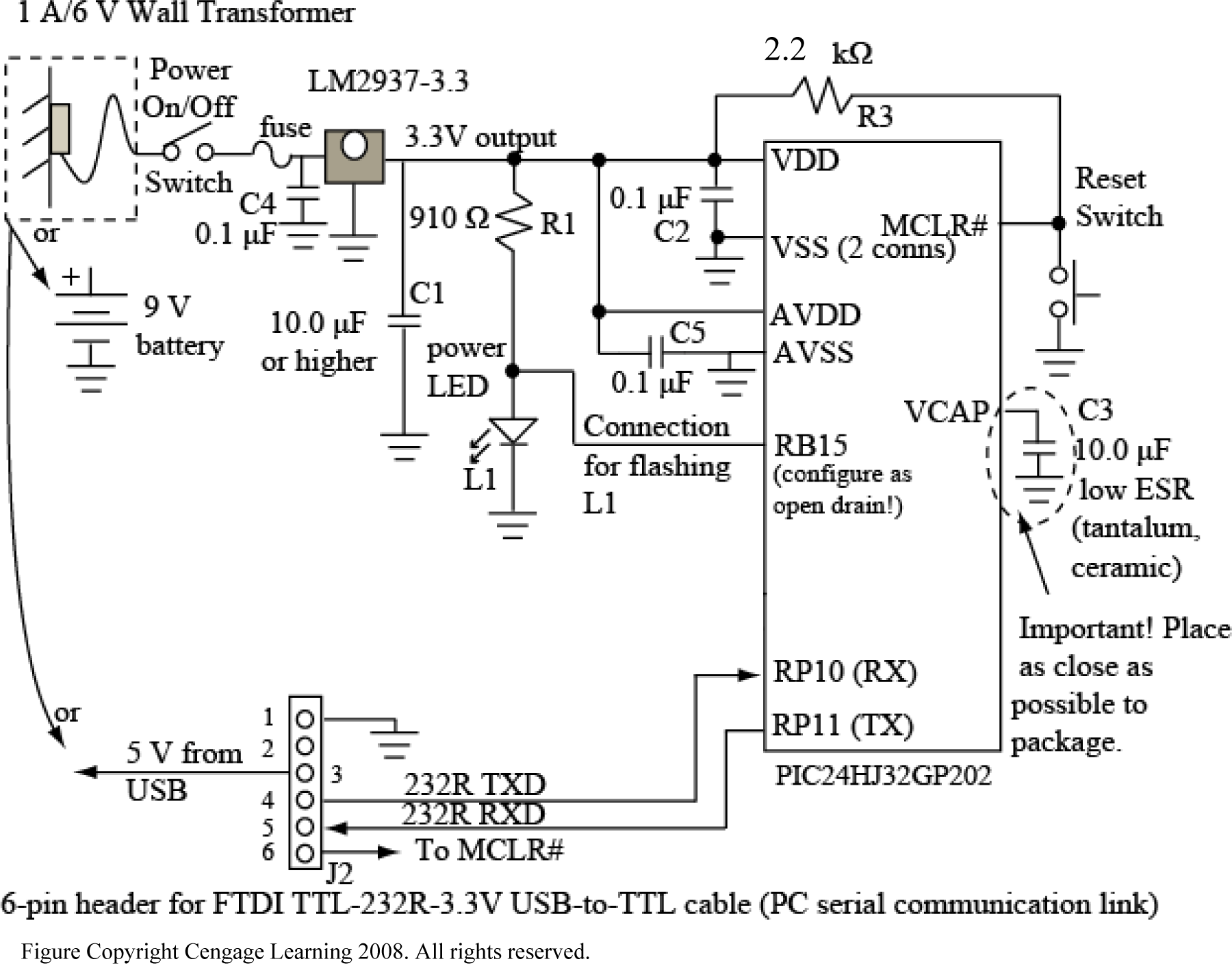
Here's a picture and schematic for our setup.
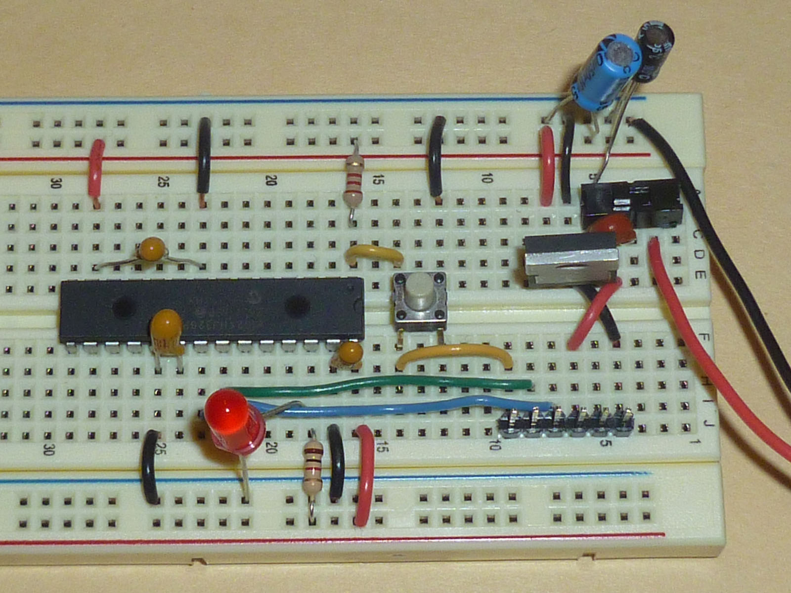
| Show your board to your instructor. |